
How to Crimp MC4 Connectors: A Step-by-Step Guide for Solar PV Cables

Updated: 3 days ago
1. Introduction: Why Proper MC4 Connector Crimping Matters
MC4 connectors are widely used in photovoltaic (PV) systems to establish electrical connections between solar panels, extension cables, and other DC-side components. They provide a practical way to connect solar cables while maintaining electrical insulation, mechanical retention, and protection against environmental exposure.
However, the reliability of an MC4 connection depends on more than the quality of the connector itself. The way the metal contact is attached to the cable conductor has a direct influence on electrical performance and long-term connection stability.
Proper MC4 connector crimping creates a secure mechanical and electrical connection between the copper conductor and the metal contact. When performed correctly, the crimp helps maintain a stable contact interface and reduces the risk of excessive contact resistance, localized heating, and premature connector failure.
Incorrect installation can cause several problems. Insufficient crimping pressure may result in a loose connection, while excessive or improperly applied pressure can damage conductor strands or deform the metal contact. Incorrect cable stripping, unsuitable crimping tools, and improperly assembled connector housings can also compromise the finished connection.
For solar cable installers, electricians, and photovoltaic system integrators, understanding the correct MC4 crimping process is essential.
This guide explains how to crimp MC4 connectors step by step, from preparing the solar PV cable and selecting the correct metal contact to assembling the connector housing and inspecting the finished connection.
Safety note: MC4 connector assembly should be performed by qualified electricians or appropriately instructed personnel. All crimping and assembly work must follow the connector manufacturer's instructions and applicable electrical safety requirements. Work on DC conductors must only be performed after the circuit has been safely isolated and verified de-energized.
2. Tools and Materials Required for MC4 Connector Crimping
Before starting the crimping process, prepare the correct connectors, solar cables, and installation tools.
Using the wrong combination of components can produce an unreliable connection even when the installation process appears correct.
2.1 MC4 Male and Female Connectors
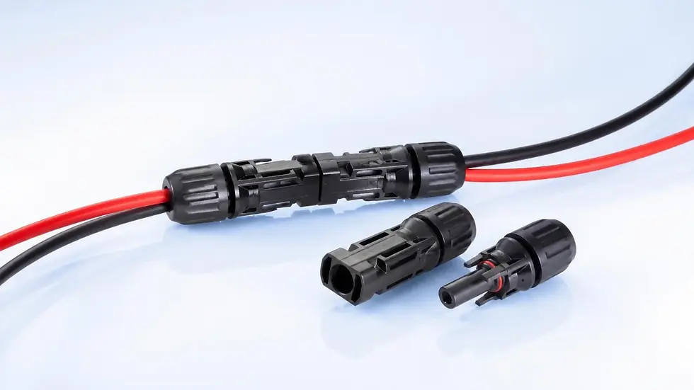
An MC4 connector assembly generally consists of several components:
Male connector housing.
Female connector housing.
Male pin contact.
Female socket contact.
Insulating components.
Cable gland and sealing components.
Cable fastening nut or cap nut.
The metal contacts establish the electrical connection between the cable conductors and the mating connector. The insulated housings provide electrical protection and mechanical support, while the sealing components help protect the connection against moisture and dust.
The connector male and female contact designs must match their corresponding housings and approved mating components.
It is important to select a complete connector set from a compatible product family rather than combining unrelated components based only on their appearance.
2.2 Solar PV Cables
The solar cable must be compatible with the selected MC4 connector and its metal contact.
Common photovoltaic cable conductor sizes include:
2.5mm²: Used in selected smaller PV cable applications.
4mm²: Commonly used for solar module connections and PV extension cables.
6mm²: Frequently selected for PV string wiring and applications requiring a larger conductor cross-section.
10mm²: Used in certain higher-current photovoltaic cable applications where the selected connector supports this conductor size.
Tinned copper conductors are commonly used in photovoltaic cables because of their suitability for outdoor electrical applications and resistance to surface oxidation.
Solar cables also typically use insulation and sheathing materials designed to withstand outdoor exposure, temperature variations, and ultraviolet radiation.
Before choosing an MC4 connector, check the following cable specifications:
Conductor cross-sectional area.
Conductor material and stranding construction.
Cable insulation thickness.
Overall cable outer diameter.
Applicable PV cable standards.
Operating voltage and temperature requirements.
The conductor size and outer cable diameter are not interchangeable specifications. A connector may support a particular conductor cross-section but still require a specific insulation diameter to achieve proper sealing.
2.3 MC4 Crimping Tool
A dedicated MC4 crimping tool is required for crimp-type connector assemblies.
Its purpose is to compress the metal contact around the copper conductor using a controlled crimping profile.
A suitable tool should provide:
A crimping die compatible with the metal contact.
A locator or positioning mechanism.
The correct crimping profile for the selected terminal.
Consistent and repeatable crimping performance.
Not all MC4 contacts use the same crimping structure. For example, Stäubli's original MC4 product documentation distinguishes between open-barrel B-Crimp contacts and closed-barrel O-Crimp contacts, which require different approved tooling combinations.
Using a tool or die intended for the wrong contact design can compromise the crimp and potentially create an unsafe electrical connection.
Staubli+1
2.4 Other Required Tools and Equipment
In addition to the crimping tool, installers should prepare:
Tool | Purpose |
Cable cutter | Cutting the solar cable cleanly |
Wire stripping tool | Removing cable insulation |
MC4 crimping tool | Attaching the metal contact |
Assembly tool | Supporting connector assembly |
Unlocking tool | Separating compatible connector housings |
Torque wrench | Applying specified assembly torque |
Inspection gauge | Checking contact insertion where specified |
Electrical testing equipment | Performing appropriate electrical checks |
Using appropriate tools helps maintain consistent installation quality and reduces the possibility of damaging the cable or connector components.
3. How to Crimp MC4 Connectors: Step-by-Step Instructions
Correct MC4 connector installation involves several stages. Each step contributes to the final connection's electrical performance, mechanical strength, and environmental protection.
The following procedure describes the general process for crimp-type MC4 connectors. Exact stripping dimensions, contact selection, crimping tools, and tightening specifications must always be taken from the installation instructions for the specific connector model.
Step 1: Prepare the Solar PV Cable
The first step is to prepare the photovoltaic cable for connector assembly.
Start by identifying the correct cable type and conductor cross-section. Confirm that the selected MC4 connector supports the cable's conductor size, stranding, and insulation diameter.
Measure the required cable length according to the installation layout. Use a suitable cable cutter to make a clean cut perpendicular to the cable.
After cutting, inspect the cable end.
Check that:
The cable insulation is not cracked or damaged.
The conductor is not exposed prematurely.
The cable end is cut evenly.
No visible moisture, dirt, or contamination is present.
The cable size matches the selected connector specification.
A clean cable end makes the subsequent stripping and contact installation process easier and more consistent.
It is also important to identify the positive and negative cable sections before assembly to prevent polarity mistakes during installation.
Step 2: Strip the Cable Insulation
After preparing the cable, remove the specified length of outer insulation from the cable end using an appropriate wire stripping tool.
The purpose is to expose the copper conductor so that it can be inserted into the metal contact for crimping.
The stripping process requires particular care because cutting or damaging individual copper strands can reduce the effective conductor cross-section and compromise the connection.
Follow these procedures:
Check the stripping length specified in the connector manufacturer's installation manual.
Adjust the stripping tool to the appropriate cable diameter.
Position the cable correctly in the stripping tool.
Remove the insulation without cutting individual copper strands.
Inspect the exposed conductor for damage or contamination.
How Long Should You Strip an MC4 Cable?
There is no single stripping length that applies to every MC4 connector.
For example, Stäubli's Original MC4 assembly instructions specify different stripping lengths depending on the contact model. Certain contact versions specify 6–7.5mm, while other versions specify 8.5–10mm.
These values demonstrate why installers must consult the exact connector installation manual instead of assuming that every MC4 terminal uses the same stripping dimension.

Cable stripping should expose the correct conductor length while keeping all copper strands intact.
An improperly stripped cable can create several problems:
Excessive exposed copper may extend beyond the intended contact area.
Insufficient exposed conductor may prevent complete insertion.
Damaged copper strands can reduce electrical contact quality.
Incorrect stripping dimensions can interfere with the connector assembly.
Always inspect the exposed conductor before proceeding.
Step 3: Select the Correct MC4 Metal Contact
Once the cable has been stripped, select the appropriate metal contact.
MC4 connector assemblies generally use two contact configurations:
Male Pin Contact
The male contact contains the pin connection used to establish electrical contact with the corresponding female socket.
Female Socket Contact
The female contact contains the socket connection designed to receive the corresponding male pin.
The contact must match the conductor cross-section and the specific connector model.
For example, a contact designed for a 4mm² PV cable should not automatically be used with a 6mm² conductor. The correct contact and approved cable combination must be confirmed from the manufacturer's technical documentation.
Also check whether the metal contact uses an open-barrel or closed-barrel crimping design.
The two designs have different crimping geometries and may require different dies and positioning accessories.
Before starting the crimping operation, verify:
Correct male or female contact.
Compatible connector housing.
Supported cable cross-section.
Approved conductor construction.
Correct crimping tool and die.
Selecting the wrong contact at this stage can compromise the entire connection, even when the remaining installation steps are performed correctly.
Step 4: Crimp the Metal Contact onto the Copper Conductor
This is the most important stage of the MC4 connector installation process.
The objective is to create a secure connection between the copper conductor and the metal contact using the correct crimping tool.
Crimping procedure:
Select the correct crimping die and locator for the contact.
Position the metal contact correctly in the crimping tool.
Secure the contact in the designated positioning mechanism.
Insert the stripped cable conductor into the contact barrel.
Ensure the conductor strands are correctly positioned.
Confirm that the contact is properly aligned with the crimping die.
Operate the crimping tool through its complete specified crimping cycle.
Release the tool and remove the completed crimp assembly.
The copper strands should be fully inserted into the intended conductor section of the contact.
The crimping operation must capture the strands securely without cutting, spreading, or excessively deforming them.

The metal contact must be correctly positioned before the crimping tool is operated.
What Does a Good MC4 Crimp Look Like?
A properly completed crimp should have the following characteristics:
The copper conductor is correctly positioned inside the contact barrel.
The contact is compressed according to the specified crimp profile.
No copper strands are missing or excessively damaged.
The metal contact has no visible cracks or severe deformation.
The conductor is mechanically retained by the contact.
Do not attempt to correct an incorrect crimp by repeatedly squeezing the contact with ordinary pliers. A defective crimp should be rejected and replaced according to the connector manufacturer's procedure.
For production or installation quality control, the crimping process may also require dimensional checks and pull-force verification using the specified inspection method.
Step 5: Inspect the Crimped Connection
Crimping is not complete until the metal contact has been inspected.
A visually acceptable connection should still be checked for correct conductor positioning, terminal deformation, and mechanical retention.
Visual Inspection
Look for:
Proper contact alignment.
Consistent crimp geometry.
Complete conductor insertion.
No exposed or stray copper strands outside the intended contact area.
No cracks, cuts, or damaged contact surfaces.
Mechanical Inspection
Where required by the connector manufacturer or the project's quality-control procedure, perform an appropriate mechanical retention or pull-force test.
The test should use the specified method and acceptance criteria. There is no universal pull-force value suitable for every MC4 contact and cable combination.
Electrical Inspection
Electrical checks should be carried out as part of the appropriate assembly verification or PV system commissioning process.
Depending on the application, these may include:
Continuity checks.
Polarity verification.
Contact resistance or other specified connection tests.
Insulation resistance tests where required and appropriate.
Testing procedures must account for connected PV modules and electrical equipment. Insulation testing should only be performed using a method suitable for the circuit configuration and connected components.
A connection that fails inspection should not be installed in the PV system.
Step 6: Insert the Crimped Contact into the MC4 Housing
After verifying the crimped connection, insert the metal contact into the appropriate connector housing.
The male pin and female socket must each be installed in their designated housing.
Follow the manufacturer's assembly instructions:
Identify the correct male or female insulating housing.
Orient the crimped contact according to the specified insertion direction.
Carefully insert the metal contact into the housing.
Push the contact until its locking mechanism engages.
Perform the specified retention check.
For Stäubli's Original MC4 connectors, the assembly instructions describe inserting the crimped contact until it engages, typically producing an audible click. The cable should then be pulled gently to verify that the metal contact is correctly retained. The manufacturer also provides a dedicated test-pin check for the assembled contact.

The crimped metal contact must be fully seated inside the corresponding insulated housing.
Do not force the contact into the housing if resistance is encountered. Incorrect orientation, an incompatible contact, or a damaged locking component may prevent correct assembly.
Step 7: Tighten the Cable Gland and Seal the Connector
The cable gland is an important part of the MC4 connector assembly because it helps retain the cable and maintain the required environmental sealing.
After the metal contact has been installed in the housing, assemble the cable gland and sealing components according to the manufacturer's instructions.
Depending on the connector design, some gland components must be placed onto the cable before the metal contact is crimped. This should be checked before starting the assembly process.
The general procedure includes:
Confirm that the sealing components are correctly positioned.
Align the cable with the connector housing.
Install the cable gland and fastening nut.
Tighten the assembly using the specified tools.
Apply the manufacturer's recommended tightening torque.
Check that the cable is correctly retained and the seal is properly seated.
The gland must be tightened according to the connector manufacturer's specified procedure.
Why Is Tightening Torque Important?
Insufficient tightening may result in inadequate cable retention or sealing.
Excessive tightening may damage the connector housing or sealing components and compromise the assembly.
There is no universal tightening torque for all MC4 products. The correct value depends on the connector design, cable dimensions, and manufacturer's installation requirements.
For example, Stäubli's Original MC4 instructions provide a typical torque range of 3.4–3.5 N·m for the specified assembly procedure. This value should not be transferred to other connector brands or models without confirmation. The instructions also recommend using a calibrated torque wrench.
Step 8: Mate the Male and Female MC4 Connectors
Once the two connector assemblies have been completed, their corresponding male and female components can be connected according to the system wiring diagram.
Before mating the connectors, verify:
Correct positive and negative cable identification.
Correct male and female connector configuration.
Approved connector compatibility.
Clean contact surfaces.
Correctly assembled locking and sealing components.
Align the connector housings and insert the matching components according to the manufacturer's instructions until the locking mechanism engages.
The connection should be secure, with no visible damage or incomplete engagement.

An assembled MC4 connector pair should be correctly aligned and fully engaged.
Important Compatibility Consideration
Not all connectors described as MC4-compatible are automatically interchangeable.
Different manufacturers may use different contact geometries, materials, locking structures, and sealing designs. Even when connectors physically fit together, the combination may not have been evaluated or approved.
Use manufacturer-approved mating combinations and avoid mixing connector brands without documented compatibility.
Step 9: Perform Final Inspection and Electrical Testing
The final step is to inspect the completed cable assembly before it enters service.
A systematic inspection helps identify mechanical defects, incorrect polarity, and assembly problems.
Mechanical Inspection
Verify that:
The connector housing is not cracked or damaged.
The metal contact is correctly retained.
The cable gland is correctly assembled.
The cable is securely held.
The connector locking mechanism is fully engaged.
Electrical Inspection
Depending on the system and applicable procedures, verify:
Correct electrical polarity.
Electrical continuity.
Proper insulation condition.
Compliance with applicable testing requirements.
For larger solar installations, quality-control procedures may also include thermal inspections during operation and follow-up inspections as part of maintenance.
Never disconnect MC4 connectors while current is flowing. These connectors are not intended to operate as load-breaking switches. PV systems can also generate hazardous DC voltage when exposed to sunlight, so qualified personnel must follow the proper isolation, verification, and commissioning procedures.
4. Common Mistakes When Crimping MC4 Connectors
Even experienced installers can encounter problems during connector assembly. Understanding common mistakes helps prevent unreliable connections and unnecessary replacement work.
4.1 Using the Wrong Crimping Tool
One of the most common mistakes is using a general-purpose crimping tool that does not match the selected MC4 metal contact.
Different contact designs may require different crimping dies and positioning accessories.
An incorrect crimp profile can deform the metal contact without producing a reliable electrical connection.
How to avoid it: Always use the crimping tool and die combination specified for the exact connector contact.
4.2 Stripping Too Much or Too Little Insulation
Incorrect stripping length may prevent the conductor from reaching the correct position inside the contact barrel.
Excessive stripping can leave unnecessary exposed conductor, while insufficient stripping can reduce the effective contact area.
How to avoid it: Follow the stripping length specified in the installation manual for the selected connector model.
4.3 Damaging Copper Strands During Stripping
Cutting individual copper strands during insulation removal reduces the effective conductor cross-section and may weaken the final connection.
How to avoid it: Use a properly adjusted stripping tool and inspect the exposed conductor before crimping.
4.4 Choosing an Incorrect Metal Contact
A contact designed for one cable size may not be suitable for another.
Even when two PV cables have similar outer diameters, their conductor cross-sections and stranding structures may differ.
How to avoid it: Match the metal contact with the actual cable conductor specifications rather than relying only on the cable's external dimensions.
4.5 Applying Incorrect Tightening Torque
Incorrect tightening can compromise the cable gland's sealing performance or damage connector components.
How to avoid it: Use the correct assembly tool and calibrated torque wrench, following the specific manufacturer's tightening instructions.
4.6 Mixing Incompatible MC4 Connector Brands
Connecting different connector brands based solely on physical fit is another important source of installation risk.
Differences in contact geometry and mechanical locking can result in unreliable connections.
How to avoid it: Use approved mating combinations and verify compatibility through manufacturer documentation.
4.7 Ignoring Final Inspection
Some installers assume that a connector is properly assembled once the metal contact has been inserted and the housing has been tightened.
However, a completed assembly still requires appropriate mechanical and electrical verification.
How to avoid it: Establish a consistent inspection process for crimp quality, contact retention, cable sealing, polarity, and electrical performance.
5. Tips for Achieving Reliable MC4 Cable Connections
Reliable MC4 installations depend on good materials, suitable tools, consistent workmanship, and proper quality control.
The following practices can help improve connection reliability across residential, commercial, and utility-scale photovoltaic projects.
5.1 Always Match Connectors with Solar Cable Specifications
The connector, metal contact, and solar cable must be compatible.
Check the conductor cross-section, material, stranding construction, and insulation diameter before beginning installation.
For example, a 4mm² PV cable and a 6mm² PV cable may require different contact configurations even when their outer appearance is similar.
5.2 Use Manufacturer-Approved Crimping Tools
The crimping tool must be suitable for the selected connector model and metal contact.
Using the correct die and locator helps maintain the required crimping geometry and improves repeatability.
For production environments, periodic inspection and maintenance of crimping tools are also important.
5.3 Follow the Correct Installation Instructions
Connector manufacturers provide specific installation procedures covering:
Cable stripping length.
Compatible conductor specifications.
Crimping tool requirements.
Contact insertion.
Cable gland assembly.
Tightening torque.
Final inspection.
These requirements should be treated as part of the connector specification rather than optional installation recommendations.
5.4 Keep Connectors Clean and Dry
Contamination during installation can affect the contact surfaces and sealing components.
Avoid allowing dust, moisture, oil, or other contaminants to enter the connector interior.
Any connector component that is contaminated or damaged should be handled according to the manufacturer's instructions.
5.5 Carry Out Proper Quality Inspection
For commercial and utility-scale photovoltaic projects, consistent installation quality is particularly important because a large number of cable connections may be installed across the entire system.
A quality-control procedure should include:
Cable size verification.
Connector model verification.
Crimping tool inspection.
Visual crimp inspection.
Contact retention verification.
Connector assembly inspection.
Appropriate electrical testing.
Maintaining installation records and inspection results can also help identify recurring workmanship problems and improve future installation processes.
6. Conclusion: Proper MC4 Crimping for Reliable Solar Cable Connections
Properly crimped MC4 connectors are an important part of reliable photovoltaic cable installations. Although the crimping process may appear straightforward, every stage requires attention to the cable specifications, metal contact design, tooling, and connector assembly requirements.
The process begins with preparing the correct solar PV cable and removing the specified length of insulation. The appropriate metal contact is then selected and crimped onto the exposed copper conductor using a compatible crimping tool.
After inspecting the crimp, the contact is inserted into the connector housing. The cable gland is assembled and tightened according to the manufacturer's instructions, followed by the mating and final verification procedures.
The most important factors to remember are:
Select a connector compatible with the solar cable.
Use the correct male or female metal contact.
Follow the specified cable stripping dimensions.
Use the approved crimping tool and die.
Inspect the crimped connection before assembly.
Apply the correct cable gland tightening torque.
Verify connector compatibility and final assembly quality.
Follow appropriate electrical safety and isolation procedures.
The quality of an MC4 connection depends on the entire assembly process, not simply the connector itself. Correct cable selection, proper installation, and systematic inspection all contribute to dependable solar DC connections.
For solar cable manufacturers, EPC contractors, distributors, and installation companies, understanding the relationship between photovoltaic cable specifications and connector requirements is essential when selecting components for a solar project.
FRCABLE provides photovoltaic cable solutions for residential, commercial, and utility-scale solar applications. When choosing solar cables for MC4 connector assemblies, buyers should consider conductor cross-section, insulation diameter, cable construction, rated voltage, and compatibility with the selected connector system.
Contact FRCABLE to discuss your PV cable specifications and requirements for different solar installation applications.
7. Frequently Asked Questions About MC4 Connector Crimping
7.1 What Is the Correct Wire Stripping Length for MC4 Connectors?
The correct stripping length depends on the MC4 connector model and metal contact design.
Different connector manufacturers may specify different stripping dimensions. Even within a single product family, different contact versions may require different lengths.
Always consult the manufacturer's installation instructions before stripping the cable.
7.2 What Crimping Tool Do You Need for MC4 Connectors?
You need a crimping tool specifically designed for the selected MC4 connector contact.
The tool must have the correct crimping die and positioning accessories for the metal contact and cable size.
Open-barrel and closed-barrel contacts may require different tooling configurations, so a general-purpose crimping tool should not be assumed suitable.
7.3 Can You Crimp MC4 Connectors Without a Special Tool?
Crimp-type MC4 connectors should be installed using the specified crimping tool.
Ordinary pliers or general-purpose tools cannot reliably reproduce the required crimping profile and pressure.
Using unsuitable tools may result in loose connections, damaged contact components, or unreliable electrical performance.
Some specialized PV connector products use alternative connection technologies, such as spring-clamp connections, but these must follow their own installation instructions and should not be confused with conventional crimp-type MC4 connectors.
7.4 Can MC4 Connectors Be Used with Both 4mm² and 6mm² Solar Cables?
Some MC4 connector models support both 4mm² and 6mm² solar cables, while others have different contact configurations for each conductor size.
The cable outer diameter must also fall within the connector's approved range to ensure proper sealing and retention.
Always check the manufacturer's cable compatibility specifications before purchasing or installing connectors.
7.5 How Do You Know If an MC4 Connector Is Properly Crimped?
A properly crimped MC4 connection should have:
Correct conductor insertion.
Consistent crimp geometry.
No visibly damaged or missing copper strands.
No severe deformation of the metal contact.
Adequate mechanical retention.
The inspection process may also include specified pull-force tests or other quality-control checks.
A visual inspection alone may not identify every defective crimp, so additional testing should be performed where required.
7.6 Can You Reuse an MC4 Connector After Crimping?
Reusing a crimped metal contact is generally not recommended.
Once a terminal has been crimped, its metal structure has undergone permanent deformation. Removing it and attempting to crimp it again may compromise mechanical retention and electrical contact quality.
For damaged or improperly crimped assemblies, follow the connector manufacturer's replacement instructions rather than attempting to reuse the contact.
7.7 Why Do MC4 Connectors Overheat After Installation?
MC4 connectors may overheat because of several installation or product-related problems.
Common causes include:
Insufficient or incorrect crimping.
Incompatible male and female connectors.
Incorrect contact and cable size matching.
Poor electrical contact.
Damaged connector components.
Loose or improperly assembled connections.
Electrical overloading or unsuitable system design.
Excessive contact resistance can generate localized heat during operation. If overheating is suspected, the affected circuit should be safely isolated and inspected by qualified personnel. Do not disconnect a connector while it is carrying current.


This is a very helpful and informative guide! The step-by-step instructions make the MC4 connector crimping process much easier to understand, especially the sections about choosing the right tools, avoiding common mistakes, and checking connection quality. I also appreciate the safety reminders, as proper installation is essential for reliable and long-lasting solar PV systems. Great resource for both beginners and experienced installers! By the way, if you're looking for a fun way to challenge your reflexes in your free time, give Geometry Dash a try!