
Aluminum PV Wire Ampacity Chart: AWG, Amps, mm² & Cable Sizing Guide

Updated: Oct 16
Selecting the correct aluminum PV wire size is not simply a matter of choosing a cable that can carry the operating current of a solar array. The conductor must have sufficient ampacity under the actual installation conditions, while also keeping voltage drop and power loss within acceptable limits.
This becomes particularly important in commercial and utility-scale photovoltaic systems, where cable runs can be long and large quantities of conductor are required. Aluminum conductors can provide an attractive alternative to copper in suitable applications, but aluminum and copper of the same AWG size do not have the same electrical characteristics.
This guide provides an aluminum wire ampacity chart covering common AWG sizes, their approximate metric cross-sectional areas in mm², and reference ampacities at 75°C and 90°C. It also explains how temperature, conductor grouping, circuit current and voltage drop affect the final aluminum PV cable size.
The ampacity values below are reference values based on NEC Table 310.16 conditions: not more than three current-carrying conductors in raceway, cable or earth and an ambient temperature of 30°C (86°F). Actual PV installations may require correction and adjustment factors.

Aluminum PV Wire Ampacity Chart
The following chart provides a useful starting point for comparing common aluminum conductor sizes.
Wire Size | Approx. Conductor Area | Aluminum Ampacity at 75°C | Aluminum Ampacity at 90°C |
12 AWG | 3.31 mm² | 20 A | 25 A |
10 AWG | 5.26 mm² | 30 A | 35 A |
8 AWG | 8.37 mm² | 40 A | 45 A |
6 AWG | 13.30 mm² | 50 A | 55 A |
4 AWG | 21.15 mm² | 65 A | 75 A |
3 AWG | 26.67 mm² | 75 A | 85 A |
2 AWG | 33.62 mm² | 90 A | 100 A |
1 AWG | 42.41 mm² | 100 A | 115 A |
1/0 AWG | 53.49 mm² | 120 A | 135 A |
2/0 AWG | 67.43 mm² | 135 A | 150 A |
3/0 AWG | 85.01 mm² | 155 A | 175 A |
4/0 AWG | 107.2 mm² | 180 A | 205 A |
The AWG conductor areas and ampacity values shown above correspond to NEC conductor data and Table 310.16 reference conditions.
Important: This is a reference ampacity chart, not a universal current-rating table for every aluminum solar cable. The final allowable current depends on the cable construction, insulation temperature rating, terminals, installation method, ambient temperature, number of current-carrying conductors and the applicable electrical code.
A cable marked for operation at 90°C does not automatically mean that the 90°C ampacity can always be used as the final circuit ampacity. Equipment and termination temperature limitations must also be checked.
What Does Aluminum Wire Ampacity Mean?
Ampacity is the maximum current a conductor can carry under specified conditions without exceeding its permitted conductor temperature.
When current flows through a conductor, electrical resistance produces heat. Increasing conductor size reduces resistance and generally allows the conductor to carry more current without exceeding its temperature limit.
This is why 4 AWG aluminum wire can carry substantially more current than 10 AWG aluminum wire.
However, conductor size is only one part of the calculation. Ampacity is also affected by installation temperature, conductor insulation, conductor grouping and the way the cable dissipates heat.
For a solar project, the question should therefore not simply be:
“How many amps can this aluminum cable carry?”
A better engineering question is:
“How much current can this aluminum PV cable safely carry under the actual conditions of this solar installation?”

AWG vs mm² for Aluminum PV Cable
AWG and mm² are two different systems used to describe conductor size.
American Wire Gauge, or AWG, is widely used in North America. Metric cable sizes expressed in mm² are common in European, Asian and other international markets.
An important difference is that the AWG system works in reverse: a smaller AWG number indicates a larger conductor.
For example:
AWG | Approx. Area |
12 AWG | 3.31 mm² |
10 AWG | 5.26 mm² |
8 AWG | 8.37 mm² |
6 AWG | 13.30 mm² |
4 AWG | 21.15 mm² |
2 AWG | 33.62 mm² |
1/0 AWG | 53.49 mm² |
4/0 AWG | 107.2 mm² |
These are conductor cross-sectional areas rather than exact commercial metric cable-size equivalents. A 6 mm² cable, for example, should not automatically be treated as electrically identical to a 10 AWG conductor simply because the dimensions are relatively close.
When comparing AWG and metric aluminum PV cables, always use the actual product datasheet rather than relying only on a nominal AWG-to-mm² conversion.
How Many Amps Can 10 AWG Aluminum Wire Carry?
Under the reference conditions used in NEC Table 310.16, 10 AWG aluminum conductor has an ampacity of approximately 30 A at 75°C and 35 A at 90°C.
That does not mean that every 10 AWG aluminum PV circuit should be designed for 35 A.
The engineer must still consider temperature correction, conductor grouping, termination ratings, overcurrent protection and PV-specific conductor-sizing requirements.
How Many Amps Can 8 AWG Aluminum Wire Carry?
8 AWG aluminum has a reference ampacity of approximately 40 A at 75°C and 45 A at 90°C under the same Table 310.16 conditions.
Its nominal conductor cross-sectional area is approximately 8.37 mm².
For a long PV cable run, however, voltage drop may require a conductor larger than the minimum size determined from ampacity alone.
How Many Amps Can 6 AWG Aluminum Wire Carry?
6 AWG aluminum has a reference ampacity of approximately 50 A at 75°C and 55 A at 90°C.
Its nominal conductor area is approximately 13.30 mm².
If a circuit requires more than the applicable 6 AWG allowable ampacity after all correction factors are considered, the conductor must be increased to the next suitable size.
How Many Amps Can 4 AWG Aluminum Wire Carry?
4 AWG aluminum is approximately 21.15 mm² and has a reference ampacity of 65 A at 75°C and 75 A at 90°C.
For higher-current PV output circuits and feeders, larger sizes such as 2 AWG, 1 AWG and 1/0 AWG may be required.
How Many Amps Can 2 AWG Aluminum Wire Carry?
2 AWG aluminum has an approximate conductor area of 33.62 mm².
Its reference ampacity is approximately 90 A at 75°C and 100 A at 90°C under the stated Table 310.16 conditions.
A common mistake is therefore to call 2 AWG aluminum simply a “100 amp wire.” The 100 A value comes from the 90°C reference column and does not mean 2 AWG aluminum is automatically appropriate for every 100 A circuit.
How Many Amps Can 1/0 Aluminum Wire Carry?
1/0 AWG aluminum has an approximate conductor area of 53.49 mm².
Its reference ampacity is approximately:
120 A at 75°C
135 A at 90°C
For still higher-current circuits, 2/0, 3/0 and 4/0 aluminum conductors provide progressively greater current-carrying capability.

Why Aluminum PV Wire Ampacity Is Not Just One Number
Solar installations can expose cable to operating conditions very different from the base conditions used in an ampacity table.
This is particularly important for PV systems because conductors may be exposed to direct sunlight, high rooftop temperatures, enclosed raceways and multiple current-carrying circuits.
Ambient Temperature
NEC Table 310.16 reference values are based on an ambient temperature of 30°C.
If the conductor operates in a hotter environment, a temperature correction factor may be required.
A PV cable operating on a hot rooftop or inside a raceway exposed to intense solar radiation may therefore have a lower practical allowable current than the number shown directly in the basic ampacity table.
Number of Current-Carrying Conductors
Several conductors installed together cannot release heat as effectively as isolated conductors.
As the number of current-carrying conductors in a raceway or cable increases, conductor ampacity may have to be adjusted.
For example, NEC-based PV guidance shows that conductor grouping can result in an 80% adjustment factor under certain conductor-count conditions.
Cable Temperature Rating
Different cable insulation systems are designed for different conductor temperatures.
A higher-temperature-rated insulation system can provide more flexibility during ampacity calculations, particularly when applying temperature correction factors.
However, the insulation rating is not the only temperature limitation in a complete circuit.
Terminal and Equipment Ratings
The terminals on disconnects, inverters, combiner boxes and other equipment must also be compatible with the conductor material, size and applicable temperature rating.
This is particularly important when using aluminum conductors. The termination must be suitable for aluminum and installed according to the equipment and connector manufacturer's requirements.
Therefore, designers should never select an aluminum PV cable by looking only at the 90°C column of an ampacity chart.
How to Calculate the Required Aluminum PV Wire Ampacity
PV conductor sizing starts with the electrical characteristics of the solar array.
For a PV source or output circuit, the maximum current is generally determined from module short-circuit current, or Isc, and the number of parallel strings.
A commonly used NEC calculation is:
Maximum PV Circuit Current = Isc × Number of Parallel Strings × 1.25
For conductor sizing, NEC 690.8 requires checking conductor ampacity against the applicable sizing rules, including the continuous-current requirement and applicable temperature and conductor adjustment factors. Under the conventional method, 125% of the calculated maximum circuit current must be considered; the larger result of the required calculations governs conductor selection.
Aluminum PV Cable Sizing Example
Assume a PV circuit has:
Module/string short-circuit current: 14 A
Number of parallel strings: 2
The maximum circuit current is:
14 A × 2 × 1.25 = 35 A
Applying a further 125% conductor-sizing requirement gives:
35 A × 1.25 = 43.75 A
Now compare 43.75 A with the aluminum ampacity table.
At the 75°C reference rating:
8 AWG aluminum = 40 A
6 AWG aluminum = 50 A
In this simplified example, 8 AWG would not meet a 43.75 A requirement using the 75°C column, while 6 AWG would.
However, this is still not the final design.
Ambient-temperature correction, conductor grouping, termination limitations, cable type and voltage drop must still be evaluated. Depending on the installation conditions, an even larger conductor may be necessary.
The applicable code edition and local Authority Having Jurisdiction should always be checked before final conductor selection because electrical-code adoption can vary by location.
Why Voltage Drop Matters in Aluminum PV Cable Sizing
Ampacity answers the safety question:
Can the cable carry the required current without exceeding its allowable temperature?
Voltage drop answers a different question:
Can the cable transmit that power efficiently over the required distance?
A conductor may satisfy ampacity requirements and still be too small for a long cable run.
Voltage drop is especially important with aluminum because aluminum has higher electrical resistance than copper for the same nominal conductor size.
The basic DC voltage-drop relationship can be expressed as:
Voltage Drop = Current × Total Circuit Resistance
For a DC circuit with separate positive and negative conductors, the total conductor length normally includes both directions of the circuit.
Therefore:
Total DC Conductor Length = One-Way Cable Length × 2
The percentage voltage drop can then be calculated as:
Voltage Drop % = Voltage Drop ÷ Operating Voltage × 100
PV design guidance commonly uses approximately 3% as a practical voltage-drop design target for many circuits, although the applicable project specification and electrical requirements should always control the final design.
Aluminum PV Voltage Drop Example
Consider an illustrative circuit using stranded 8 AWG aluminum conductor.
NEC conductor data gives approximately 4.204 Ω/km at 75°C for the referenced stranded aluminum conductor.
Assume:
Operating current = 20 A
One-way cable length = 100 m
Round-trip DC conductor length = 200 m, or 0.2 km
The approximate voltage drop is:
20 A × 4.204 Ω/km × 0.2 km = 16.82 V
If the circuit operates at 600 V:
16.82 ÷ 600 × 100 ≈ 2.80%
The example demonstrates why cable length must be checked even when ampacity is adequate.
Actual calculations should use resistance data for the specific conductor construction and its expected operating temperature.
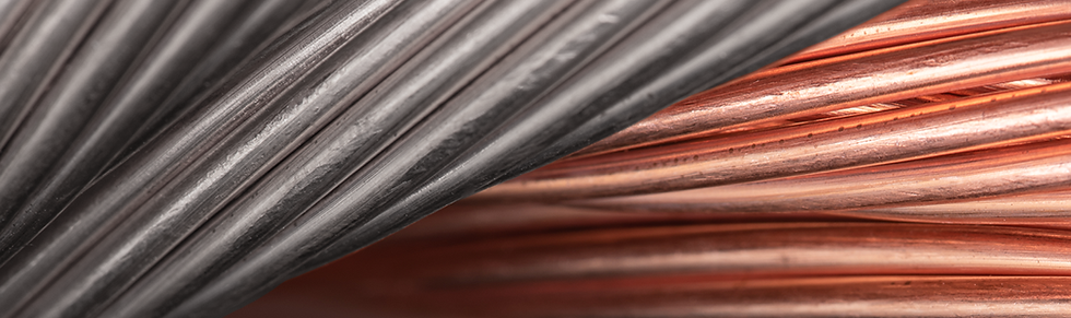
Aluminum vs Copper PV Wire Ampacity
Copper has higher electrical conductivity than aluminum. Therefore, when comparing the same AWG size under equivalent conditions, copper generally has a higher ampacity.
Wire Size | Copper at 75°C | Aluminum at 75°C |
10 AWG | 35 A | 30 A |
8 AWG | 50 A | 40 A |
6 AWG | 65 A | 50 A |
4 AWG | 85 A | 65 A |
2 AWG | 115 A | 90 A |
1/0 AWG | 150 A | 120 A |
4/0 AWG | 230 A | 180 A |
These values illustrate why a copper PV conductor normally cannot be replaced with aluminum simply by selecting the same AWG size.
If a project changes from copper to aluminum, the engineer should recalculate conductor size based on ampacity, voltage drop, circuit length, temperature conditions and termination requirements.
A larger aluminum conductor may still provide an economically attractive solution for suitable projects because conductor cost is only one part of overall system design.
Is Aluminum PV Wire Suitable for Solar Systems?
Aluminum conductors are widely used in commercial and utility electrical applications, especially where project scale makes conductor material and cost important considerations. Proper conductor sizing and termination are essential.
For PV applications, the cable must also be specifically designed and certified for its intended solar environment.
Ordinary aluminum building wire should not automatically be treated as photovoltaic wire simply because it has sufficient conductor ampacity.
The complete PV cable must meet the required electrical, thermal, mechanical and environmental performance requirements for the intended project.

Aluminum PV Cable for 1500V Solar Systems
Higher-voltage DC architectures are widely used in large photovoltaic projects because they allow more modules to be connected in series and can reduce current for a given power level.
FRCABLE offers TÜV 2PfG 2642 PV1500DC-AL aluminum solar cable designed for 1500V DC photovoltaic applications. The product uses a stranded Class 5 aluminum-alloy conductor with cross-linked insulation and jacket materials and is specified for an operating temperature range of -40°C to 90°C.
Current FRCABLE PV1500DC-AL sizes include:
FRCABLE Cable Size | Product AWG Reference | Rated Voltage |
4 mm² | 12 AWG reference | 1500V DC |
6 mm² | 10 AWG reference | 1500V DC |
10 mm² | 8 AWG reference | 1500V DC |
FRCABLE publishes maximum conductor resistance values of 7.20 Ω/km for 4 mm², 4.80 Ω/km for 6 mm² and 3.08 Ω/km for 10 mm² on the current product specification page.
These product sizes should be selected using their actual certified product characteristics and project design requirements rather than assigning them the NEC ampacity of a nominally similar AWG size.
FRCABLE also offers aluminum PV wire configurations for projects requiring UL 4703 products.
How to Choose the Correct Aluminum PV Cable Size
A reliable cable selection should begin with the system rather than the cable.
First determine the maximum PV circuit current from the module or array electrical data. Then determine the minimum conductor ampacity required by the applicable electrical code.
After that, apply the relevant temperature and conductor-grouping corrections for the actual installation.
The next step is to verify that the selected cable insulation and all connected terminals are suitable for the expected operating conditions and conductor material.
Finally, calculate voltage drop using the real circuit length and cable resistance.
If the minimum cable size required by voltage drop is larger than the size required by ampacity, the larger conductor should be used.
In other words:
Required Cable Size = The larger size required by ampacity or voltage-drop calculations.
This approach is particularly important for long-distance solar cable runs, where voltage drop rather than thermal ampacity can become the controlling design factor.
Is Bigger Aluminum PV Wire Always Better?
Electrically, increasing conductor size reduces resistance and can reduce voltage drop and power loss.
However, oversized cable also increases material consumption, cable diameter, connector requirements, installation handling and project cost.
The objective is therefore not to specify the largest possible conductor.
The objective is to identify the smallest practical cable that safely satisfies ampacity, voltage-drop, mechanical, connection and regulatory requirements with an appropriate engineering margin.
For large PV projects involving thousands of meters of cable, optimizing conductor size can have a significant effect on overall balance-of-system design.
Frequently Asked Questions
What is the ampacity of aluminum PV wire?
There is no single ampacity for all aluminum PV wire. Ampacity depends on conductor size, temperature rating, installation method, ambient temperature, conductor grouping and termination limitations. For example, under NEC Table 310.16 reference conditions, 8 AWG aluminum is rated at 40 A at 75°C and 45 A at 90°C.
How many amps can 10 AWG aluminum wire carry?
10 AWG aluminum has a reference ampacity of approximately 30 A at 75°C and 35 A at 90°C under NEC Table 310.16 conditions. The allowable current in a specific solar installation may be lower after applicable adjustment and correction factors are applied.
How many amps can 8 AWG aluminum wire carry?
8 AWG aluminum has a reference ampacity of approximately 40 A at 75°C and 45 A at 90°C.
How many amps can 6 AWG aluminum wire carry?
6 AWG aluminum has a reference ampacity of approximately 50 A at 75°C and 55 A at 90°C.
How many amps can 4 AWG aluminum wire carry?
4 AWG aluminum has a reference ampacity of approximately 65 A at 75°C and 75 A at 90°C.
What size aluminum wire is used for 100 amps?
Under NEC Table 310.16 reference conditions, 2 AWG aluminum corresponds to 90 A at 75°C and 100 A at 90°C, while 1 AWG aluminum corresponds to 100 A at 75°C and 115 A at 90°C. This does not mean either size can automatically be specified for every 100 A PV circuit. Terminal ratings, temperature correction, installation conditions, overcurrent protection and other applicable requirements must be checked.
Is aluminum wire larger than copper for the same ampacity?
Usually, yes. Because aluminum has lower conductivity than copper, a larger aluminum conductor is generally required to achieve comparable ampacity and voltage-drop performance.
Can copper PV wire be replaced with aluminum of the same AWG size?
Not automatically. Aluminum and copper of the same AWG size have different ampacity and resistance values. A copper-to-aluminum conversion requires a new calculation for ampacity, voltage drop, cable length and termination compatibility.
Does cable length change the required aluminum PV wire size?
Yes. Cable length does not change the basic conductor ampacity shown in a reference table, but longer cable runs increase resistance and voltage drop. As a result, a long PV circuit may require a larger conductor even when a smaller conductor already satisfies the ampacity requirement.
Is 90°C ampacity always the correct rating for solar cable?
No. A 90°C insulation rating can be used as part of conductor-sizing and correction calculations where permitted, but the final allowable ampacity may be limited by connected equipment, terminals or other code requirements.
Can aluminum PV cable be used in 1500V solar systems?
Yes, when the cable is specifically designed, rated and certified for that application. FRCABLE's PV1500DC-AL aluminum solar cable is designed for 1500V DC photovoltaic applications and is available in 4 mm², 6 mm² and 10 mm² configurations.
Final Takeaway
An aluminum PV wire ampacity chart is a useful starting point, but it should never be the only tool used to select a photovoltaic cable.
Correct cable sizing requires engineers to evaluate the maximum circuit current, conductor ampacity, insulation temperature rating, ambient temperature, number of current-carrying conductors, terminal compatibility, cable length and voltage drop.
For short cable runs, ampacity may determine the minimum conductor size. For long solar-array runs, voltage drop may require a larger conductor. When changing from copper to aluminum, the conductor size should always be recalculated rather than replaced on a one-to-one AWG basis.
For commercial and utility-scale PV projects, properly selected aluminum PV cable can provide an effective solution where cost, conductor size, cable weight and long-distance transmission all need to be balanced.
Need Help Selecting Aluminum PV Cable?
FRCABLE supplies aluminum solar cable solutions for photovoltaic applications, including TÜV 2PfG 2642 PV1500DC-AL 1500V DC cable and UL PV wire options.
Send us your system voltage, maximum current, cable length, required cable size and applicable standard, and the FRCABLE team can help identify an appropriate cable specification for your solar project.


Comments