
Wire Ampacity Chart: AWG Copper & Aluminum Wire Amp Ratings

Choosing the correct wire size is not simply a matter of matching an AWG number to an amperage rating. Conductor material, insulation temperature rating, terminal temperature, ambient temperature, the number of current-carrying conductors, continuous load and voltage drop can all affect the final conductor size.
A wire ampacity chart provides the starting point.
Under NEC Table 310.16, copper and aluminum conductors have different allowable ampacities at 60°C, 75°C and 90°C. Understanding how these ratings work helps electricians, engineers, contractors and buyers select conductors that can safely carry the required electrical load.
This guide explains the most common AWG ampacity ratings and, more importantly, how to use them correctly.
Quick answer: A wire ampacity chart shows the maximum current an insulated conductor can carry under specified installation and temperature conditions without exceeding its allowable operating temperature.
Wire Size Amperage Chart by AWG / kcmil
The two tables below give base ampacities for copper and aluminum conductors at each temperature rating, covering common sizes from 14 AWG through 1000 kcmil. Find your gauge in the first column, then read across to the column that matches your terminal temperature rating.
Copper Ampacity
Wire Size (AWG / kcmil) | 60°C (A) | 75°C (A) | 90°C (A) |
14 AWG | 15 | 20 | 25 |
12 AWG | 20 | 25 | 30 |
10 AWG | 30 | 35 | 40 |
8 AWG | 40 | 50 | 55 |
6 AWG | 55 | 65 | 75 |
4 AWG | 70 | 85 | 95 |
3 AWG | 85 | 100 | 115 |
2 AWG | 95 | 115 | 130 |
1 AWG | 110 | 130 | 145 |
1/0 AWG | 125 | 150 | 170 |
2/0 AWG | 145 | 175 | 195 |
3/0 AWG | 165 | 200 | 225 |
4/0 AWG | 195 | 230 | 260 |
250 kcmil | 215 | 255 | 290 |
300 kcmil | 240 | 285 | 320 |
350 kcmil | 260 | 310 | 350 |
400 kcmil | 280 | 335 | 380 |
500 kcmil | 320 | 380 | 430 |
600 kcmil | 355 | 420 | 475 |
700 kcmil | 385 | 460 | 520 |
750 kcmil | 400 | 475 | 535 |
800 kcmil | 410 | 490 | 555 |
900 kcmil | 435 | 520 | 585 |
1000 kcmil | 455 | 545 | 615 |
Aluminum / Copper-Clad Aluminum Ampacity
Wire Size (AWG / kcmil) | 60°C (A) | 75°C (A) | 90°C (A) |
12 AWG | 15 | 20 | 25 |
10 AWG | 25 | 30 | 35 |
8 AWG | 35 | 40 | 45 |
6 AWG | 40 | 50 | 55 |
4 AWG | 55 | 65 | 75 |
3 AWG | 65 | 75 | 85 |
2 AWG | 75 | 90 | 100 |
1 AWG | 85 | 100 | 115 |
1/0 AWG | 100 | 120 | 135 |
2/0 AWG | 115 | 135 | 150 |
3/0 AWG | 130 | 155 | 175 |
4/0 AWG | 150 | 180 | 205 |
250 kcmil | 170 | 205 | 230 |
300 kcmil | 195 | 230 | 260 |
350 kcmil | 210 | 250 | 280 |
400 kcmil | 225 | 270 | 305 |
500 kcmil | 260 | 310 | 350 |
600 kcmil | 285 | 340 | 385 |
700 kcmil | 315 | 375 | 425 |
750 kcmil | 320 | 385 | 435 |
800 kcmil | 330 | 395 | 445 |
900 kcmil | 355 | 425 | 480 |
1000 kcmil | 375 | 445 | 500 |
What Is Wire Ampacity?

Wire ampacity is the maximum electrical current, measured in amperes, that a conductor can carry continuously under specified conditions without exceeding its permitted temperature.
When electrical current passes through a conductor, electrical resistance generates heat.
The amount of heat increases as current increases. If the conductor carries more current than it was designed for, excessive temperature can accelerate insulation aging and potentially damage the cable or surrounding electrical equipment.
This is why conductor size and ampacity must be considered together.
In general:
Larger conductor → lower electrical resistance → greater current-carrying capacity
AWG numbering can initially seem confusing because the relationship is reversed:
Smaller AWG number → larger conductor
For example:
12 AWG is larger than 14 AWG.
10 AWG is larger than 12 AWG.
6 AWG is larger than 8 AWG.
1 AWG is larger than 2 AWG.
After 1 AWG, conductor sizes continue as 1/0, 2/0, 3/0 and 4/0.
Why Are There 60°C, 75°C and 90°C Ampacity Ratings?
One of the most important parts of a wire ampacity chart is the temperature column.
A common mistake is to assume that a cable marked with 90°C insulation can always be sized according to the 90°C ampacity column.
That is not necessarily correct.
The allowable conductor ampacity may also be limited by the temperature rating of the equipment terminals.
60°C Ampacity
The 60°C column is associated with lower-temperature terminations and certain wiring applications.
It is particularly important for smaller conductors and equipment where the termination is not identified for a higher temperature rating.
75°C Ampacity
The 75°C column is widely used for many modern electrical equipment terminations, including appropriately marked breakers, switches, distribution equipment and lugs.
For this reason, the 75°C column is often a useful reference when comparing practical conductor sizes.
90°C Ampacity
Many modern conductor insulation types can have a 90°C rating.
Examples may include THHN/THWN-2, XHHW-2 and similar high-temperature insulation systems.
However, a 90°C insulation rating does not automatically mean the conductor can be loaded to the full 90°C table ampacity.
The 90°C value is frequently important when applying adjustment or correction factors, while the final permissible ampacity may still be limited by a 75°C or 60°C termination.
Common Copper Wire Amp Ratings
For users who only need a quick answer, these are some of the most frequently searched copper conductor sizes.
How Many Amps Can 14 Gauge Wire Handle?
14 AWG copper has base ampacity values of:
15A at 60°C
20A at 75°C
25A at 90°C
However, small-conductor overcurrent protection requirements must also be considered. In typical NEC applications, 14 AWG copper is commonly associated with a maximum 15A overcurrent device unless a specific exception applies.
How Many Amps Can 12 Gauge Wire Handle?
12 AWG copper is rated:
20A at 60°C
25A at 75°C
30A at 90°C
For many ordinary branch circuits, 12 AWG copper is commonly used with 20A overcurrent protection.
How Many Amps Can 10 Gauge Wire Handle?
10 AWG copper has base ampacity ratings of:
30A at 60°C
35A at 75°C
40A at 90°C
Although the insulation may permit a higher temperature-based ampacity, NEC small-conductor protection rules are important when selecting the breaker.
How Many Amps Can 8 Gauge Wire Handle?
8 AWG copper has an ampacity of approximately:
40A at 60°C
50A at 75°C
55A at 90°C
This is why 8 AWG copper frequently appears when people search for 40 amp wire size or 50 amp wire size.
Whether it is suitable depends on conductor type, terminal ratings, continuous loading and installation conditions.
How Many Amps Can 6 Gauge Wire Handle?
6 AWG copper is rated approximately:
55A at 60°C
65A at 75°C
75A at 90°C
It is commonly considered for higher-current feeders and equipment circuits, but the final selection must still consider the applicable installation rules.
How Many Amps Can 4 Gauge Wire Handle?
4 AWG copper has base ampacity values of:
70A at 60°C
85A at 75°C
95A at 90°C
For aluminum, the equivalent ampacity is lower at the same AWG size.

Copper vs Aluminum Wire Ampacity
Copper and aluminum conductors of the same AWG size do not have the same ampacity.
Copper has higher electrical conductivity, so a copper conductor can normally carry more current than an aluminum conductor of the same nominal AWG size.
For example, at 75°C:
Wire Size | Copper | Aluminum |
10 AWG | 35A | 30A |
8 AWG | 50A | 40A |
6 AWG | 65A | 50A |
4 AWG | 85A | 65A |
2 AWG | 115A | 90A |
1/0 AWG | 150A | 120A |
4/0 AWG | 230A | 180A |
This does not mean aluminum cable is inferior.
Aluminum conductors are widely used for feeders, service-entrance conductors and larger power distribution systems because they can offer advantages in weight and material cost.
The important rule is:
Do not replace a copper conductor with the same AWG size in aluminum without recalculating the required conductor size.
The terminals and connectors must also be suitable for the conductor material being used.
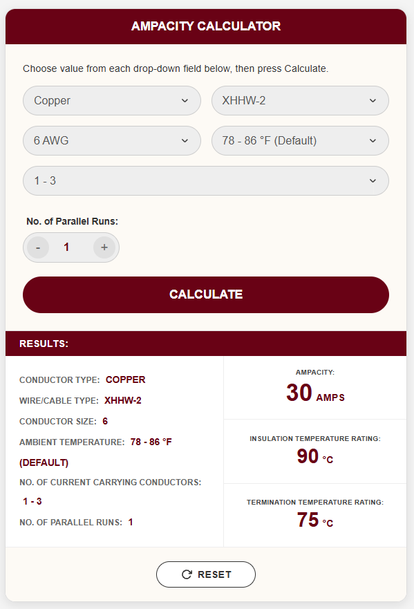
What Wire Size Do I Need for 30, 40, 50, 60 or 100 Amps?
This is one of the most common questions related to wire ampacity.
Using the 75°C column as a simple ampacity comparison, the minimum conductor whose table ampacity meets the stated current would be approximately:
Required Ampacity | Copper | Aluminum |
30A | 10 AWG* | 10 AWG* |
40A | 8 AWG | 8 AWG |
50A | 8 AWG | 6 AWG |
60A | 6 AWG | 4 AWG |
70A | 4 AWG | 3 AWG |
100A | 3 AWG | 1 AWG |
125A | 1 AWG | 2/0 AWG |
150A | 1/0 AWG | 3/0 AWG |
200A | 3/0 AWG | 250 kcmil |
*Small-conductor overcurrent protection rules can limit actual breaker sizing even where a temperature column shows a higher ampacity.
This table is useful for comparison, but it should not be treated as a universal circuit design table.
A 100A installation, for example, may require different conductor sizing depending on whether it is a feeder, service, motor circuit, residential service, continuous load or another application covered by a specific NEC rule.
Continuous Loads Can Require a Larger Wire
Another factor often missed when reading an ampacity chart is continuous loading.
A load expected to operate continuously for three hours or more is generally treated as a continuous load under NEC rules.
For many branch circuits and feeders, conductor sizing is based on:
125% of continuous load + 100% of noncontinuous load
For example, imagine equipment draws 40A continuously.
The conductor-sizing load would normally begin at:
40A × 125% = 50A
You would therefore look for a conductor with sufficient allowable ampacity for at least 50A, subject to the other applicable requirements.
This is one reason why simply matching the operating current directly to a wire ampacity number can result in incorrect conductor selection.
Ambient Temperature Can Reduce Wire Ampacity
NEC ampacity tables are based on specified reference conditions.
When conductors operate in a hotter environment, their ability to dissipate heat decreases.
Examples include:
Rooftop conduit
Industrial machinery
Boiler rooms
Hot production facilities
Enclosed electrical cabinets
Outdoor installations in high-temperature climates
In these environments, temperature correction factors may need to be applied.
A conductor that appears large enough according to the standard ampacity chart may therefore need to be increased in size after temperature correction.
More Than Three Current-Carrying Conductors Can Require Derating
The number of loaded conductors installed together can also influence allowable ampacity.
When several current-carrying conductors are bundled in the same raceway or cable, the heat produced by each conductor becomes more difficult to dissipate.
NEC adjustment factors can therefore reduce the permissible ampacity when the number of current-carrying conductors exceeds the conditions assumed by the base ampacity table.
This is especially important in:
Large electrical panels
Industrial control systems
Cable trays
Multi-circuit conduits
Commercial buildings
Data centers
Manufacturing facilities
Ignoring conductor-count adjustment is one of the most common ways an apparently correct wire size becomes undersized in an actual installation.
Wire Ampacity vs Voltage Drop
Ampacity and voltage drop are related to wire sizing, but they are not the same thing.
Ampacity determines whether the conductor can safely carry the current.
Voltage drop determines how much voltage is lost along the conductor.
A conductor may satisfy the ampacity requirement and still be too small for a very long circuit.
Longer conductors have greater resistance, which causes a larger voltage drop.
Important variables include:
Circuit current
Conductor length
Copper or aluminum conductor
Conductor cross-sectional area
System voltage
Single-phase or three-phase system
For long cable runs, increasing the conductor size can reduce resistance and voltage drop.
This is particularly important for:
Solar installations
EV charging circuits
Pumps
Motors
Outdoor equipment
Agricultural installations
Industrial machinery
Long feeder circuits
Therefore, conductor selection should normally include both an ampacity check and a voltage-drop check.
Does Voltage Change the Ampacity of a Wire?
Not directly.
A conductor's ampacity is primarily determined by its ability to manage heat under the applicable installation conditions.
For example, the basic ampacity of a conductor does not automatically double simply because a system changes from 120V to 240V.
However, voltage affects the current required to deliver a given amount of power.
For a simplified single-phase resistive load:
Current (A) = Power (W) ÷ Voltage (V)
For example, a 4,800W load would draw approximately:
40A at 120V
20A at 240V
Therefore, a higher system voltage can reduce current for the same power requirement, which may allow a smaller conductor depending on the complete circuit design.
Does Stranded Wire Carry More Amps Than Solid Wire?
Not automatically.
Ampacity depends on conductor material, conductor size, insulation rating and installation conditions rather than simply whether the conductor is solid or stranded.
Stranded construction is often chosen because it provides greater flexibility, particularly for larger cable sizes and applications involving installation bends or equipment connections.
The conductor must still meet the required cross-sectional area and applicable ampacity requirements.
AWG vs mm²: Are They the Same?
No.
AWG and square millimeters are two different conductor-sizing systems.
AWG is widely used in North America, while mm² conductor sizes are commonly used in IEC markets.
Approximate conversions are useful for communication, but an AWG ampacity value should not simply be transferred to the nearest metric conductor size.
IEC cable ampacity can depend heavily on:
Installation method
Conductor material
Insulation material
Ambient temperature
Number of loaded conductors
Cable arrangement
Installation in air, conduit, wall or ground
When purchasing cables for international projects, always identify whether the project specification follows NEC/UL, IEC, EN or another local standard.
How to Choose the Correct Wire Size
A reliable conductor-sizing process should consider more than the ampacity chart.
1. Determine the Design Load
Calculate the maximum expected circuit current.
Identify continuous and noncontinuous loads where required.
2. Identify Copper or Aluminum
Do not assume identical AWG sizes have the same current capacity.
3. Check the Conductor Insulation Rating
Determine whether the conductor is rated for 60°C, 75°C, 90°C or another specified operating condition.
4. Check Terminal Temperature Ratings
The breaker, disconnect, switch, terminal block or connected equipment can limit the conductor ampacity.
5. Apply Ambient Temperature Correction
High ambient temperatures can reduce allowable ampacity.
6. Apply Conductor-Count Adjustment
Multiple current-carrying conductors installed together can require derating.
7. Check Overcurrent Protection Requirements
The circuit breaker or fuse must comply with the applicable conductor and equipment protection requirements.
8. Calculate Voltage Drop
Long cable runs may require a larger conductor even when the ampacity requirement has already been satisfied.
9. Check Application-Specific NEC Rules
Motors, transformers, photovoltaic systems, EV charging equipment, HVAC systems and service conductors can have additional sizing requirements.
Common Wire Sizing Mistakes
Using the 90°C Column Without Checking the Terminals
A 90°C cable does not automatically mean the connected breaker or equipment terminal is rated for 90°C.
Choosing Wire Only by Breaker Size
The load type, continuous-load requirement and equipment-specific NEC rules also matter.
Ignoring Ambient Temperature
A conductor installed in a hot environment may require correction.
Ignoring Bundled Conductors
Multiple current-carrying conductors in the same raceway can require ampacity adjustment.
Ignoring Voltage Drop
A wire may technically carry the load but still produce unacceptable voltage drop over a long distance.
Using Copper and Aluminum Ratings Interchangeably
The same AWG size normally has different ampacity ratings depending on conductor material.
Assuming AWG and mm² Ampacity Are Equivalent
The nearest metric size does not automatically have the same allowable ampacity under IEC installation rules.
Frequently Asked Questions
What is the ampacity of 12 AWG copper wire?
According to the common NEC ampacity table values, 12 AWG copper is rated at 20A at 60°C, 25A at 75°C and 30A at 90°C. Small-conductor overcurrent protection rules still apply, so 12 AWG copper is commonly associated with 20A branch-circuit protection in standard applications.
How many amps can 10 AWG copper wire handle?
10 AWG copper has base ampacity values of 30A at 60°C, 35A at 75°C and 40A at 90°C. The permitted circuit rating depends on the applicable NEC rules and installation.
How many amps can 8 AWG copper wire handle?
8 AWG copper is rated at approximately 40A at 60°C, 50A at 75°C and 55A at 90°C under the standard table conditions.
How many amps can 6 AWG copper wire handle?
6 AWG copper has base ampacity values of approximately 55A at 60°C, 65A at 75°C and 75A at 90°C.
What size copper wire is commonly associated with 100 amps?
In the NEC 75°C ampacity column, 3 AWG copper has a base ampacity of 100A. However, the actual conductor size for a 100A circuit depends on the application, terminal rating, correction factors and other applicable NEC provisions.
What size aluminum wire is needed for 100 amps?
In the 75°C ampacity column, 1 AWG aluminum has a base ampacity of 100A. Specific applications may permit or require different sizing rules, so the installation should always be checked against the applicable code.
Is copper wire better than aluminum wire?
Neither material is universally better.
Copper offers higher conductivity and typically allows a smaller conductor for the same ampacity. Aluminum is lighter and can be more economical for larger feeders and power-distribution applications.
The correct choice depends on current requirements, installation method, cost, weight, equipment compatibility and project specifications.
Can I use the 90°C ampacity if my cable is rated 90°C?
Not automatically. The conductor insulation may be rated 90°C while the equipment terminals are rated only 75°C. The allowable final ampacity must comply with the applicable termination-temperature requirements.
Does a longer cable need to be larger?
It may. Cable length does not automatically change the conductor's base ampacity, but longer conductors have greater resistance and therefore greater voltage drop. Increasing conductor size is a common method of reducing voltage drop on long circuits.
Final Thoughts
A wire ampacity chart is an essential starting point for selecting electrical conductors, but the number in the table should never be considered in isolation.
Correct wire sizing involves evaluating:
Load current → continuous load → conductor material → insulation temperature → terminal rating → ambient temperature → conductor count → overcurrent protection → voltage drop.
For a quick comparison, the NEC ampacity table can tell you how much current a particular AWG copper or aluminum conductor can carry under defined conditions.
For the final design, however, the conductor must be checked against the specific electrical system, equipment markings, installation environment and the NEC edition adopted by the local authority.
If you are selecting wire or cable for an electrical project, provide the required current, voltage, conductor material, cable length, installation method, ambient temperature and applicable standard. These details make it possible to determine a much more reliable conductor size instead of choosing wire from amperage alone.


Drift Boss players, did you know a 90°C cable rating does not always mean you can use the 90°C ampacity? What do you think?