UL PV Wires Standards: 2025 NEC Compliance Requirements
- Waseem Raheel
- Jan 28
- 15 min read
What Are UL PV Wires? Definition and Core Functions
Navigating the complex wiring requirements for a solar installation can be daunting. At the heart of a safe and efficient photovoltaic (PV) system lies a specialized component: the UL PV wire. This article defines this critical cable, explains its core functions, and clarifies why it's not interchangeable with standard building wire.
1. Core Definition of a Photovoltaic Wire
1.1 Formal Definition and Purpose
A UL PV wire is a single-conductor cable specifically designed and listed for interconnecting components within solar arrays. Its primary purpose is to safely carry direct current (DC) power from solar panels to combiner boxes or inverters. These wires are engineered to withstand the unique environmental stressors of outdoor solar applications.
Underwriters Laboratories (UL) standard UL 4703 governs their construction, testing, and certification, ensuring they meet rigorous safety and performance benchmarks.
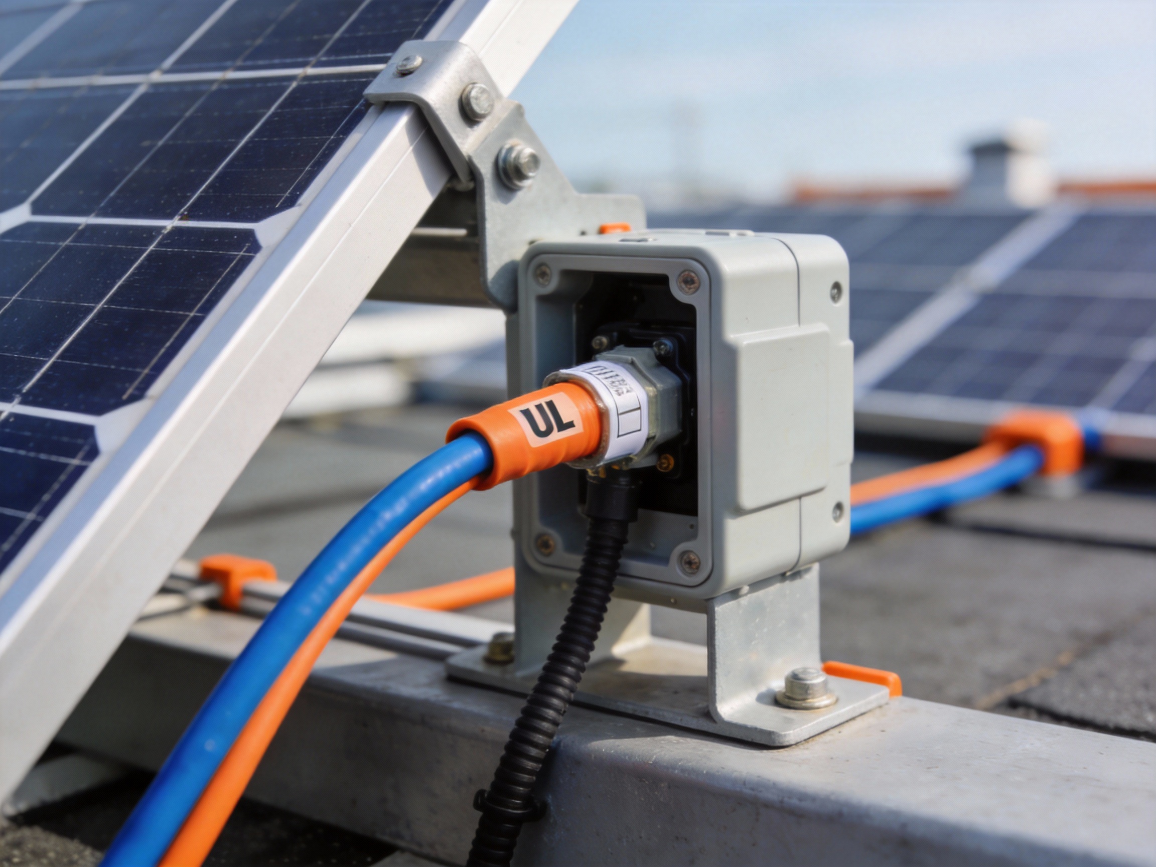
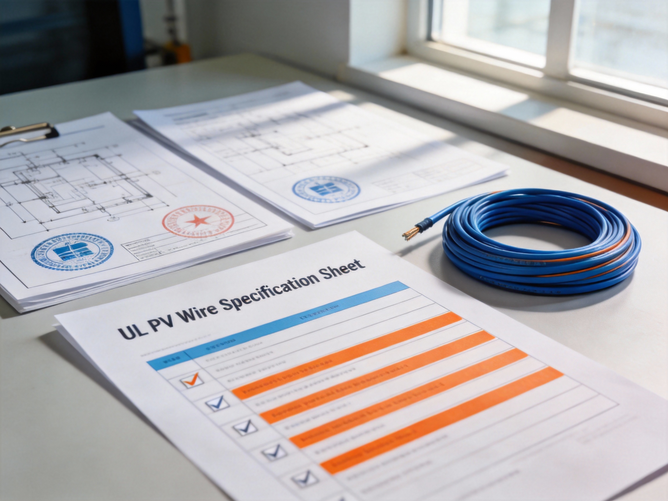
Pro Tip: Always look for the “UL” mark and “PV WIRE” or “PV CABLE” printed on the cable jacket. This is your guarantee that the product has been independently tested and certified for solar use.
1.2 Key Physical and Environmental Ratings
UL PV wires possess distinct ratings that differentiate them. They are rated for wet locations and can be exposed to sunlight and buried directly in soil without conduit. A critical rating is their temperature range; they are typically rated for 90°C in wet conditions and 150°C in dry conditions, far exceeding standard wire.
Their insulation and jacket are also sunlight-resistant (UV-resistant) and formulated to resist ozone, moisture, and temperature extremes common in rooftop and field installations.
2. Primary Functions in a Solar Array
2.1 Interconnecting Solar Panels
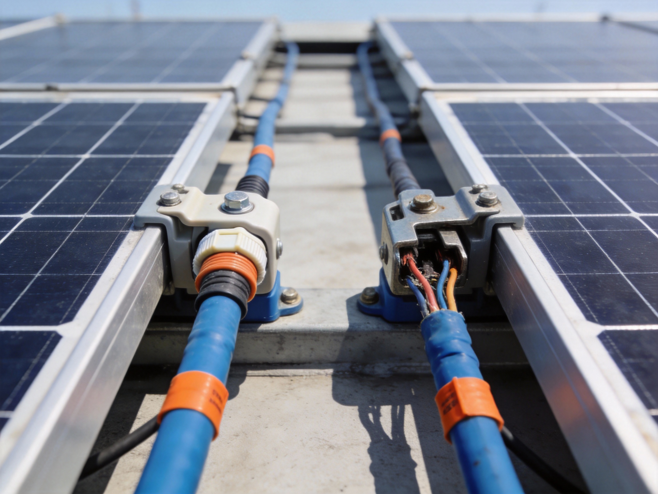
The core function is creating the electrical links between individual solar modules. PV wires, often with pre-attached MC4 connectors, run from the junction box on one panel to the next, forming strings. These series connections increase the DC voltage to optimal levels for the inverter.
This inter-array wiring is permanently exposed to the elements, making the environmental durability of PV wire non-negotiable for long-term system integrity.
2.2 Handling High DC Voltage and Current
Solar arrays operate at high DC voltages, often up to 600V, 1000V, or even 1500V for utility-scale systems. PV wire insulation is specifically tested for these high DC voltage stresses. It also manages the continuous DC current generated by the panels, with ampacity ratings determined under sunlight exposure conditions.
Using wire not rated for these specific conditions can lead to insulation degradation, posing serious shock and fire risks over time.
3. PV Wire vs. USE-2: A Critical Distinction
3.1 Understanding USE-2 Wire
USE-2 (Underground Service Entrance) cable is another single-conductor cable sometimes used in solar. It shares some similarities, like a 90°C wet rating and suitability for direct burial. Historically, it was a common, accepted choice for solar interconnections under the National Electrical Code (NEC).
However, its older standard (UL 854) does not include all the specialized tests required for dedicated PV applications.
3.2 Why PV Wire is the Superior Choice
While both may look similar, UL 4703 PV wire is the modern, enhanced standard. It includes mandatory testing for sunlight resistance, higher dry location temperature ratings (150°C), and flame retardancy that USE-2 may not uniformly meet. The NEC now explicitly recognizes PV wire as the preferred and most comprehensive option.
The table below summarizes the key differences:
Feature | UL PV Wire (UL 4703) | USE-2 Wire (UL 854) |
Primary Design Purpose | Photovoltaic array interconnections | Underground service entrance |
Sunlight (UV) Resistance | Required and tested | Not required by standard |
Dry Location Temp Rating | Up to 150°C | Typically 90°C |
Flame Test | Required (VW-1) | Not required by standard |
NEC Recognition for Solar | Explicitly listed (Article 690) | Historically used, but PV wire is preferred |
In summary, UL PV wire is the engineered solution for solar energy, providing the durability, safety, and compliance needed for a reliable system. Choosing the correct wire is a foundational step in ensuring your solar investment is protected for decades.
Why UL Standards for PV Wires Are Non-Negotiable for Safety
In the demanding world of solar energy, every component must withstand decades of environmental abuse. The wires connecting your photovoltaic (PV) modules are the system's circulatory system, and their failure can lead to catastrophic results. This is why adherence to UL standards, particularly UL 4703 for PV Wire, is not a suggestion but a fundamental requirement for safety, performance, and long-term reliability.
1. The UL 4703 Standard: A Benchmark for Harsh Environments
The UL 4703 standard is specifically engineered for the unique stresses of solar installations. Unlike general-purpose building wire, PV wire must perform reliably for 25+ years while exposed to UV radiation, extreme temperatures, and moisture.
1.1 Core Test Requirements for Durability
UL 4703 subjects PV wire to a battery of accelerated life tests that simulate decades of field exposure. Key requirements include sunlight (UV) resistance testing to prevent insulation cracking and wet insulation resistance verification to ensure safety during rain. The standard also mandates a long-term thermal aging test at 90°C or 105°C to verify the conductor and insulation's lifespan.
These tests collectively ensure the wire maintains its electrical and mechanical integrity, preventing premature failures that could lead to ground faults or arcing.
1.2 Ensuring Fire Safety and Flame Retardancy
Fire safety is paramount, especially for rooftop installations. UL 4703 includes rigorous flame retardancy tests, such as the vertical flame test, to ensure the wire does not propagate fire. The insulation and jacket materials are formulated to be self-extinguishing.
As noted in UL documentation, the standard evaluates the "ability of the wire to resist the spread of fire along its length," a critical factor in limiting damage and protecting property.
2. The High Cost of Non-Compliance
Using wire that does not meet UL 4703 introduces significant, often hidden, risks. The initial cost savings are dramatically outweighed by the potential for system failure, safety hazards, and financial liability.
2.1 Documented Failure Rates and Risks
Industry studies and insurance data indicate that non-compliant wire is a leading contributor to PV system failures. Common issues include insulation degradation from UV exposure, leading to conductor exposure and ground faults. Moisture ingress in substandard wire can cause corrosion and increased resistance, creating hot spots.
One analysis of field failures suggested that wiring-related issues could account for over 15% of preventable system downtime and safety incidents.
2.2 Beyond the Wire: System-Wide Implications
The failure of a single wire can compromise an entire array or create a serious fire ignition source. Non-compliant wire may also void equipment warranties and invalidate building and electrical permits. Furthermore, it can lead to significant liability in the event of a fire, as insurers and authorities will investigate code compliance.
Pro Tip: Always look for the "UL" mark and the specific "PV Wire" designation printed on the cable jacket. This is your visual guarantee that the product has been independently tested and certified to UL 4703, not just constructed with similar-looking materials.
Ultimately, specifying UL-listed PV wire is the most effective risk mitigation strategy, ensuring your solar investment is built on a foundation of proven safety and durability.
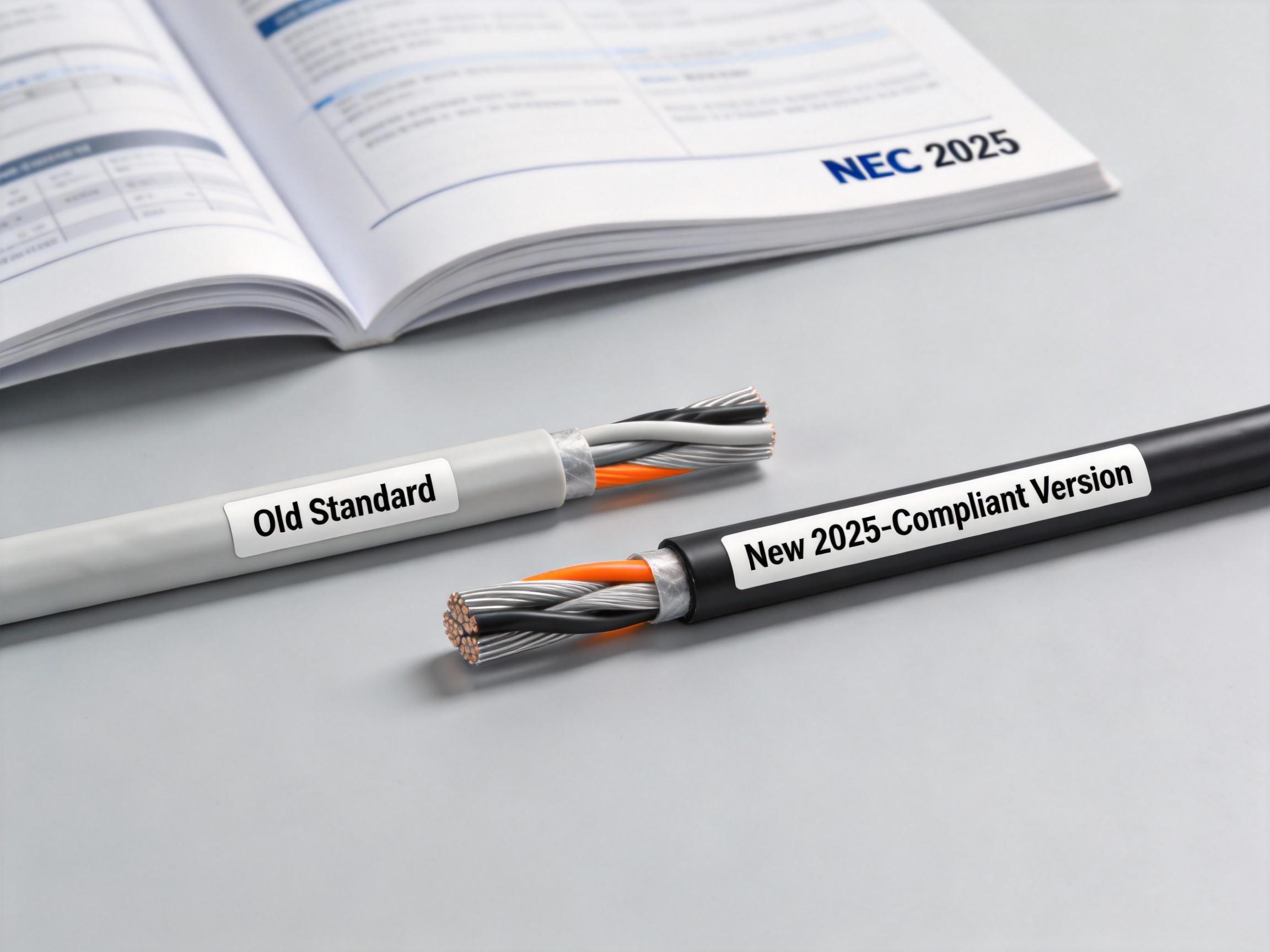
Key Changes in the 2025 NEC for Photovoltaic Wiring
The 2025 edition of the National Electrical Code (NEC) introduces pivotal updates to Article 690, directly impacting photovoltaic (PV) system safety and design. These revisions, driven by evolving technology and field experience, mandate a closer look at conductor selection, installation methods, and labeling. For installers and designers, understanding these changes is crucial for ensuring compliance and system longevity.
1. New Conductor Requirements and Clarifications
This section covers the most significant updates to the types and uses of conductors within PV arrays, focusing on enhanced safety and clarity.
1.1 Clarification on PV Wire and USE-2 Usage
The 2025 NEC provides explicit guidance on the use of PV Wire and USE-2 cables. While both are permitted for module interconnections, the code now more clearly delineates their intended environments. PV Wire, with its superior sunlight resistance and flexibility, is emphasized for exposed, within-array wiring.
This clarification in Section 690.31(C) helps prevent the misapplication of USE-2, which may degrade faster under direct UV exposure, potentially leading to insulation failure.
1.2 Ampacity Adjustments for Temperature
Ampacity correction for ambient temperature has been refined. The 2025 code requires more precise application of temperature correction factors based on the actual installed environment, not just default assumptions.
For example, conductors on a dark rooftop in a hot climate may require a derating factor as high as 0.58 or more. This change underscores the need for accurate site-specific calculations to prevent conductor overheating.
Pro Tip: Always use the manufacturer's stated temperature rating for your specific PV wire when performing ampacity calculations. Do not assume a default value, as ratings can vary between 90°C, 105°C, or higher.
2. Enhanced Installation and Labeling Mandates
Beyond conductor selection, the new code strengthens requirements for how systems are physically installed and identified, improving safety for first responders and maintenance personnel.
2.1 Rapid Shutdown Labeling Updates
Building on existing rapid shutdown rules, the 2025 NEC adds specific labeling requirements for equipment that achieves the reduced voltage state. Labels must now clearly indicate the boundaries of controlled and uncontrolled conductors.
This enhances safety by ensuring firefighters can quickly identify which sections of the array are de-energized, a critical consideration during emergency operations on a building.
2.2 DC Combiner Box Circuit Directory
A new requirement mandates that DC combiner boxes include a circuit directory. This directory must identify the source circuit for each overcurrent protective device within the box.
This simple administrative change drastically improves system troubleshooting and maintenance, allowing technicians to quickly isolate specific strings without tracing every wire.
3. Summary of Key 2025 NEC Changes for PV
The following table and list consolidate the major updates relevant to PV wiring, providing a clear at-a-glance comparison to the previous 2023 code cycle.
3.1 2023 vs. 2025 NEC Requirement Comparison
Topic | 2023 NEC | 2025 NEC Key Change |
Conductor Application | PV Wire and USE-2 both listed for PV use. | Enhanced clarity favoring PV Wire for exposed applications; stricter guidance on USE-2 limitations. |
Ampacity Calculation | Ambient temperature correction required. | Emphasis on precise, site-specific temperature correction factors to prevent overheating. |
Rapid Shutdown Labeling | General labeling requirements existed. | New, specific labels required to delineate controlled vs. uncontrolled conductor boundaries. |
DC Combiner Boxes | Circuit identification was a best practice. | Circuit directory now mandated inside each DC combiner box (New in 690.15). |
3.2 Quick-Reference List of Updates
Clarified PV Wire vs. USE-2 applications in exposed environments (690.31).
Stricter ambient temperature ampacity corrections for conductor sizing.
Enhanced rapid shutdown labeling for clearer hazard identification.
Mandatory circuit directory inside DC combiner boxes (690.15).
Revised requirements for bipolar system grounding and overcurrent protection.
Staying ahead of these 2025 NEC changes is not just about compliance—it's a fundamental step in designing safer, more reliable, and easier-to-maintain photovoltaic systems. Always consult the full, adopted code for your jurisdiction before finalizing any design.
How to Identify Compliant UL PV Wire Markings and Labels
Correctly identifying compliant PV wire markings is a critical safety and code-compliance step for installers and inspectors. These permanent ink-printed labels on the cable jacket provide a verifiable record of the product's construction, certification, and performance limits. This guide provides a clear, step-by-step method for interpreting these markings to ensure you are using genuine, approved components.
1. Preparation and Visual Inspection
1.1 Locate and Clean the Markings
First, find the manufacturer's printing on the wire jacket, which repeats every few feet. Ensure the surface is clean and dry for a clear reading. Use a flashlight if working in low-light conditions like an attic or junction box.
Look for a continuous, legible print run. Faded, smudged, or inconsistently spaced text can be a red flag for a non-compliant or counterfeit product.
1.2 Understand the Required Marking Elements
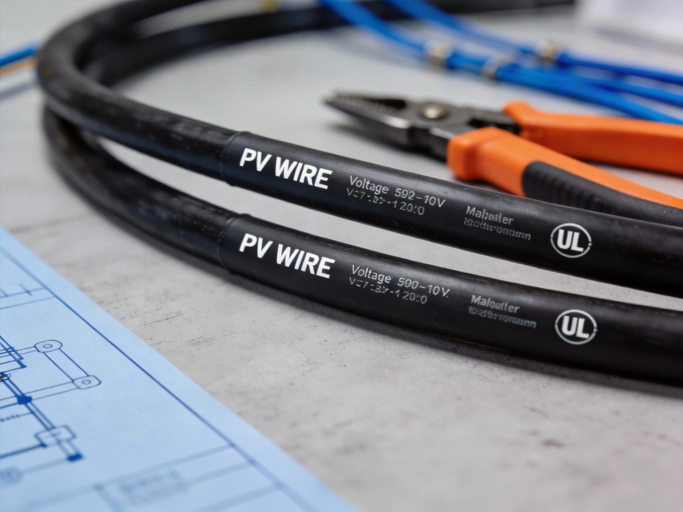
A compliant UL-listed PV Wire must have specific, permanently printed information. The core elements to look for include the wire type designation, the UL Listing Mark, voltage rating, conductor size, and temperature rating.
Other crucial markings are the manufacturer's name or trademark and the sunlight resistance designation ("Sun Res" or "W"). Missing any of these is a major compliance issue.
2. Step-by-Step Verification of Key Markings
2.1 Verify the "PV Wire" Designation and UL Mark
Confirm the cable is explicitly marked as "PV WIRE" or "PHOTOVOLTAIC WIRE." This differentiates it from USE-2 or other cables. Immediately adjacent, you must see the official UL Listed symbol (the "UL" in a circle).
Pro Tip: The "UL" mark may be followed by a file number (e.g., E123456). You can verify this number on UL's online certification directory to confirm the product's active listing status.
2.2 Check Temperature and Sunlight Resistance Ratings
PV Wire must be rated for wet locations and high temperatures. Look for a temperature rating of 90°C (194°F) or higher, often printed as "90°C WET" or "90°C". The sunlight resistance is equally vital, indicated by "Sun Res," "Sunlight Resistant," or the suffix "W."
These ratings are non-negotiable for long-term, safe outdoor exposure. Cables without them will degrade rapidly, posing fire and shock risks.
3. Final Compliance Checklist and Warnings
3.1 Use a Verification Checklist
Systematically check each item against this list before installation. A compliant PV Wire marking must include all of the following:
"PV WIRE" or "PHOTOVOLTAIC WIRE" designation
UL Listed Mark (often with file number)
Voltage Rating (e.g., 600V, 1000V, 2000V)
Conductor Size (e.g., 10 AWG, 1/0 AWG)
Temperature Rating (e.g., 90°C WET, 125°C)
Sunlight Resistance ("Sun Res" or "W")
Manufacturer's Name/Trademark
3.2 Heed Warnings on Counterfeit Products
Be extremely wary of wires with blurry printing, misspellings, or missing critical marks like the UL symbol. Counterfeit or mislabeled products are a serious market problem and will not provide the promised safety performance.
Using non-compliant wire voids system warranties, violates the National Electrical Code (NEC), and creates significant liability. Always source materials from reputable, authorized distributors.
By following this verification process, you ensure the foundational safety and longevity of the PV array. Always document your inspections as part of a quality assurance protocol.
Step-by-Step Guide to Sizing PV Wires for NEC 2025 Compliance
Correctly sizing your PV wire is a non-negotiable requirement for safety, performance, and code compliance. This guide provides a clear, actionable methodology based on NEC 2025 principles, focusing on current, voltage drop, and ambient temperature adjustments to determine the correct AWG.
1. Preparation and Data Gathering
1.1 Determine Maximum Circuit Current
The starting point is calculating the maximum current your wire must carry. Per NEC 690.8(A)(1), multiply the PV module's short-circuit current (Isc) by 125% for continuous operation. For parallel strings, sum the adjusted currents. This value, known as the ampacity requirement, is your baseline for wire sizing.
For example, a single string with an Isc of 10A requires a wire sized for 12.5A (10A x 1.25). This step ensures the wire can handle long-term thermal stress.
1.2 Identify Ambient Temperature and Conduit Type
Real-world conditions derate a wire's current-carrying capacity. You must know the installation's ambient temperature and whether the wire is in free air or inside conduit. Temperature correction factors are found in NEC Table 310.16. Conduit fill also requires derating per NEC 310.15(C)(1).
A common scenario is a rooftop installation where ambient temperatures can exceed 40°C (104°F). This will significantly impact your final wire size selection.
2. Core Sizing Calculation Process
2.1 Apply Temperature and Derating Factors
Take your maximum circuit current from step 1.1 and apply the correction factors from step 1.2. Divide the required current by the product of all applicable derating factors. The result is the minimum required ampacity your chosen wire must have <em>before</em> temperature correction.
Pro Tip: Always use the worst-case ambient temperature for your location, not an average. Sizing for peak conditions prevents overheating and ensures long-term reliability.
2.2 Select Wire Size from NEC Table 310.16
Using the calculated minimum required ampacity, consult the 75°C column of NEC Table 310.16 (for most PV wire ratings). Choose a wire with a listed ampacity equal to or greater than your calculated value. This table provides the base ampacity for conductors at 30°C ambient.
For instance, if your adjusted calculation demands a minimum of 18A, a 12 AWG copper wire (ampacity: 25A) would be the minimum compliant size at this stage.
3. Final Verification and Voltage Drop Check
3.1 Perform Voltage Drop Calculation
Code-minimum size may not be performance-sufficient. Excessive voltage drop reduces system efficiency. The industry best practice is to limit DC voltage drop to 2% or less. Use the standard voltage drop formula, incorporating circuit length, current, and the chosen wire's resistance.
Key variables are one-way circuit length (in feet), the current from 1.1, and the uncoated copper resistance (in Ω/kFT) for your selected AWG.
3.2 Adjust Size and Finalize Selection
If the voltage drop exceeds your target (e.g., 2%), you must increase the wire size to a larger AWG and recalculate. This iterative process ensures both NEC compliance and optimal system performance. The final wire size is the larger of the ampacity-derived size and the voltage-drop-derived size.
Common adjustments involve upsizing from 10 AWG to 8 AWG for long string runs to maintain acceptable voltage levels, even if the smaller size technically meets ampacity rules.
Following this step-by-step process, which integrates NEC Tables 310.16 and 690.8, ensures your PV wire selection is safe, compliant, and efficient for the life of the installation.
Common PV Wire Compliance Failures and How to Avoid Them
Failing a PV system inspection due to wiring issues is a costly and frustrating setback. These failures often stem from a handful of common, preventable mistakes. By understanding these pitfalls and implementing proactive checks, installers can ensure their work meets NEC Article 690 and UL standards for a smooth first-pass approval.
1. Preparation and Planning Phase
1.1 Using Incorrect Wire Type or Rating
The most fundamental failure is using a wire not rated for photovoltaic applications. Standard building wire (THHN/THWN-2) lacks the sunlight resistance and wet-location rating required for outdoor PV runs. Inspectors will fail any installation not using UL 4703-listed PV Wire or USE-2/RHH/RHW-2 cables specifically marked for solar use.
This mistake is easily avoided by verifying the cable's printed markings. Look for "PV WIRE" or "PV CABLE," the UL logo, and a voltage rating of at least 1.8kV.
1.2 Inadequate Conduit Fill Calculations
Overfilling conduit is a frequent code violation that creates heat buildup and makes wire pulling nearly impossible. The NEC Chapter 9, Table 1 provides maximum fill percentages (e.g., 40% for three or more conductors). Exceeding these limits is a guaranteed inspection red flag.
Always perform fill calculations before installation. For complex runs, using a larger conduit size or an additional raceway is a simple fix that saves time during the final inspection.
2. Installation Execution Errors
2.1 Improper Grounding and Bonding
Faulty equipment grounding conductor (EGC) connections are a critical safety failure. This includes loose lugs, incorrect sizing, or missing bonding jumpers across metallic enclosures. The EGC must provide a low-impedance path to clear ground faults.
Use a torque wrench on all terminations per manufacturer specs and verify continuity from each module frame back to the main grounding electrode with a multimeter.
2.2 Insufficient Strain Relief and Support
Wires entering junction boxes or inverters without proper clamps or connectors violate NEC 300.14 and 314.17. This lack of strain relief can lead to pulled connections and arcing over time. Similarly, exposed cable runs must be supported at code-specified intervals.
Install listed cable connectors for the specific cable type and diameter. For rooftop runs, use UV-resistant clips or ties at intervals not exceeding 4.5 feet to prevent sagging and wind damage.
Pro Tip: Conduct a "tug test" on every cable connector after installation. A proper connection should hold firm under moderate hand pressure, ensuring the inspector's pull test will pass.
3. Final Verification and Labeling
3.1 Missing or Incorrect System Labeling
The NEC mandates specific warnings and identification for PV systems. Common omissions include the lack of a "PHOTOVOLTAIC POWER SYSTEM" plaque at the service disconnect, missing DC voltage and current labels on combiner boxes, or unmarked disconnect switches.
Create a labeling checklist from NEC 690.53 and 705.10. Use durable, weatherproof labels and verify all required warnings are present and legible before the inspector arrives.
3.2 Failing Pre-Inspection Electrical Tests
Inspectors will verify key electrical measurements. Coming unprepared with failed test results is a direct path to rejection. Essential pre-checks include confirming correct polarity, measuring DC insulation resistance (should be >1 Megohm), and verifying open-circuit voltage is within the inverter's input range.
Document all test results. Presenting a signed commissioning report with passing metrics demonstrates professionalism and speeds up the inspection process.
3.3 Pre-Inspection Checklist
Run through this final list before calling for inspection to catch common oversights:
Verify all exposed PV wire is marked "PV WIRE" or "PV CABLE" (UL 4703).
Check conduit fill percentages and secure all cable supports.
Torque and tug-test all terminations, especially grounding connections.
Confirm all required warning labels and system plaques are installed.
Have documented proof of passing electrical tests (polarity, insulation resistance).
By methodically addressing these common failure points during planning, installation, and final verification, you can transform inspection day from a stressful exam into a mere formality.
Case Study: Upgrading a Solar Array to Meet 2025 NEC Standards
This case study examines a real-world solar panel wiring retrofit project for a 25kW commercial rooftop array. The primary goal was to replace outdated wiring with new UL PV Wires to ensure compliance with the upcoming 2025 National Electrical Code (NEC) standards. We'll walk through the project specifics, the challenges encountered, and the key outcomes.
1. Project Overview and Initial Assessment
1.1 System Specifications and Original Wiring
The system was a 25kW rooftop installation with 72 panels, originally commissioned in 2018. The existing wiring consisted of USE-2 cables that were not rated for the higher temperature and fire safety requirements anticipated in the 2025 NEC.
A thermal scan revealed hotspots at several junction boxes, indicating potential insulation degradation under load.
1.2 The Core Compliance Problem
The main issue was the wire's fire rating. The old USE-2 cables did not meet the more stringent flame propagation tests that will be required for photovoltaic systems in the 2025 code cycle.
This created a significant liability and safety risk, making a proactive upgrade a financial and operational necessity before the new standards took effect.
2. The Retrofit Process and Solutions
2.1 Material Selection and Planning
We selected UL 4703-listed PV Wire with a 90°C wet rating and a verified flame-retardant jacket. A total of 1,200 feet of 10 AWG wire was required for the module interconnections and home runs.
<blockquote><p>Pro Tip: Always order 10-15% more wire than your calculated length. Real-world routing around conduits, racks, and existing infrastructure always consumes more cable than the straight-line diagram suggests.
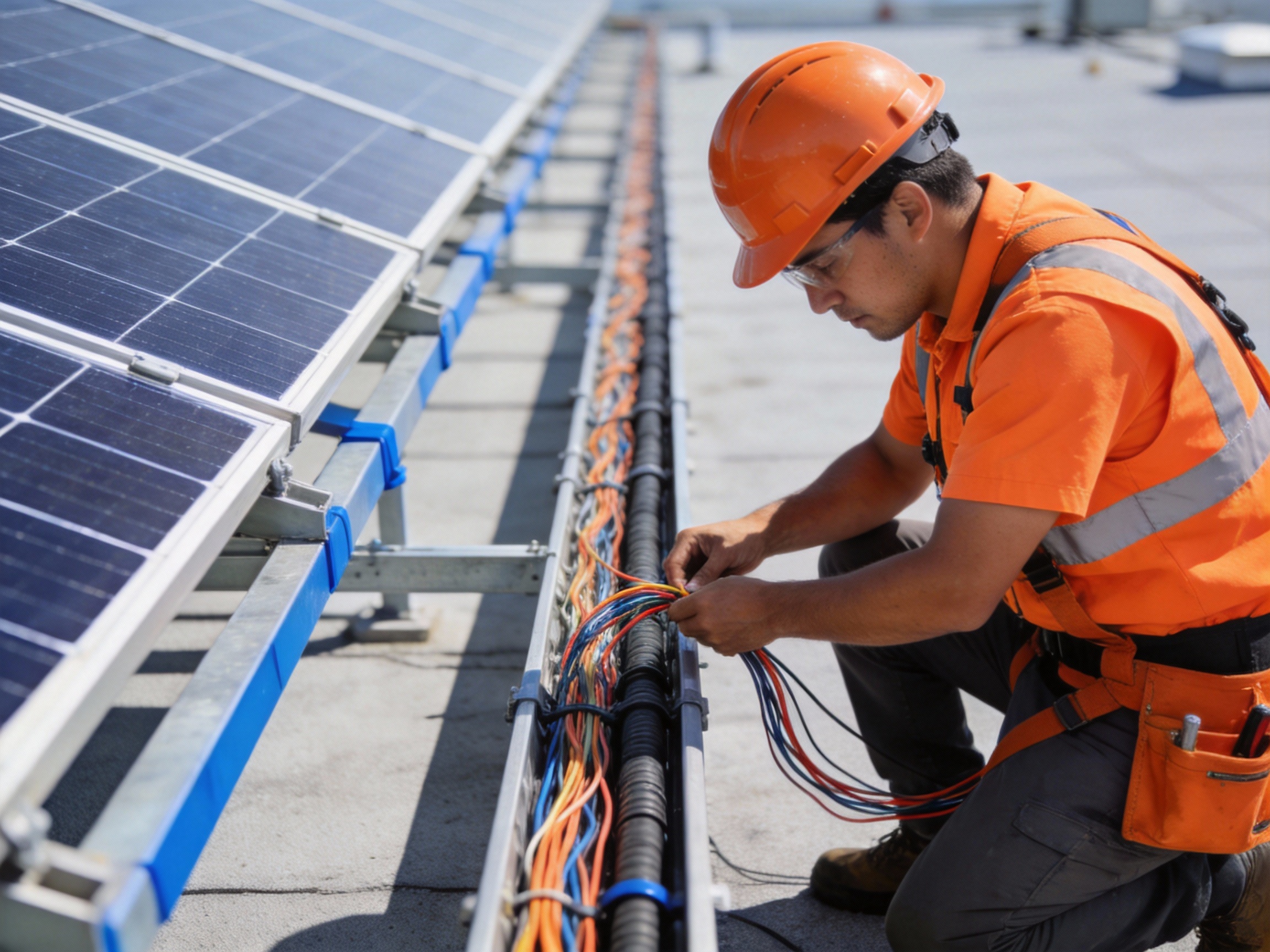
2.2 On-Site Execution and Challenges
The primary challenge was accessing and replacing wires within tightly packed cable trays without disrupting the system's daily energy production. We sequenced the work in three parallel strings to minimize downtime.
Unexpected hurdles included weathered cable clamps that needed replacement and re-labeling every circuit to maintain accurate system documentation.
3. Outcomes and Lessons Learned
3.1 Compliance and Performance Results
Post-upgrade, the system passed all inspection points for the 2025 NEC, specifically meeting UL 4703 requirements. The new wiring also reduced voltage drop by approximately 0.5%, translating to a slight increase in annual energy yield.
The thermal hotspots were eliminated, confirming the superior heat tolerance of the new PV Wire insulation.
3.2 Key Takeaways for Installers
This retrofit underscored several critical lessons for future projects. Proactive upgrades based on code forecasts can prevent costly emergency replacements.
Key considerations for any wiring retrofit include: Audit First: Conduct a full thermal and electrical assessment of the existing system. Future-Proof Materials: Specify wires that exceed current code to anticipate upcoming changes. Plan for Access: Logistical access to old wiring is often the biggest time and cost variable.
This project demonstrates that a strategic, planned upgrade is a manageable investment that ensures long-term safety, compliance, and system performance.
