Solar Panel Connectors: UL 6703 and IEC 62852 Standards Explained
- Waseem Raheel
- Jan 26
- 21 min read
What Are Solar Panel Connectors and Why Are They Critical?
In a photovoltaic (PV) system, the flow of electricity from the solar panels to the inverter is only as reliable as its weakest link. While panels and inverters receive most of the attention, the solar panel connectors that link them are critical, yet often overlooked, components. These specialized photovoltaic connectors are engineered to handle high DC currents, resist environmental stress, and maintain a safe, low-resistance connection for decades.

1. Defining the Photovoltaic Connector
1.1 Core Function and Location
A solar panel connector is a gender-coded, quick-connect coupling designed specifically for the DC side of a PV array. Its primary function is to create a secure, weatherproof electrical link between solar panels and the system wiring. In a typical string configuration, connectors are located at the end of each panel's junction box output cables and are used to daisy-chain modules together.
This creates a continuous electrical path from the first panel to the combiner box or inverter, forming the backbone of the system's power collection network.
1.2 Key Components and Materials
Modern PV connectors are precision-engineered assemblies. The critical components include a UV-stabilized plastic housing, a metal contact pin/socket, and a sealing gasket. The housing material, typically polyamide (PA) or similar, must withstand decades of sun exposure without becoming brittle.
The internal metal contacts are often tin-plated copper or silver-plated copper to ensure excellent conductivity and corrosion resistance, which is vital for minimizing power loss as heat.
2. Why Connectors Are a Critical System Component
2.1 The Primary Risk: Connection Failure
Poorly made or degraded connectors are a leading cause of PV system underperformance and safety hazards. A high-resistance connection generates excessive heat, which can melt housings, damage cables, and in extreme cases, initiate an electrical fire. Industry analysis suggests that connection-related issues can account for a significant percentage of system failures.
For instance, a study by the German Fraunhofer Institute noted that connector failures were a recurrent theme in field inspections of underperforming systems, highlighting their operational criticality.
2.2 Impact on Safety and Performance
The consequences of connector failure extend beyond simple power loss. Electrically, a faulty connection increases system resistance, directly reducing energy yield. From a safety perspective, it creates a potential point for arcing and overheating, which compromises the entire installation's fire safety.
Reliable connectors ensure the system operates at its designed voltage and current, protecting the investment and guaranteeing long-term, safe energy production.
Pro Tip: Always inspect the IP (Ingress Protection) rating of a connector. For long-term rooftop durability, FR-CABLE engineers recommend a minimum of IP67, which guarantees protection against dust ingress and temporary immersion in water, crucial for withstanding harsh weather cycles.
3. Essential Connector Specifications
3.1 Electrical and Mechanical Ratings
Selecting the correct connector requires verifying its ratings against your system's specifications. The current rating (Amps) and voltage rating (Volts DC) must exceed the maximum system output. Equally important is the connector's compatibility with your cable's cross-sectional area (e.g., 4mm², 6mm²).
Mechanical specifications, such as mating cycles (the number of times it can be connected/disconnected reliably), also indicate long-term durability and contact integrity.
3.2 Compliance and Intermateability
For safety and insurance purposes, connectors should be certified to recognized standards. In the US market, look for UL 6703 certification. A critical, often misunderstood concept is intermateability—the ability of different brands to connect safely.
Use only connectors from the same manufacturer and product line
Never force together connectors from different brands, even if they appear similar
Verify that both the male and female components have matching certifications
Mixing incompatible brands is a major installation error that can lead to poor contact, overheating, and voided warranties.
Understanding the fundamental role and specifications of solar panel connectors is the first step in ensuring a safe, high-performing PV system. Their selection and installation demand the same level of scrutiny as the major components they interconnect.
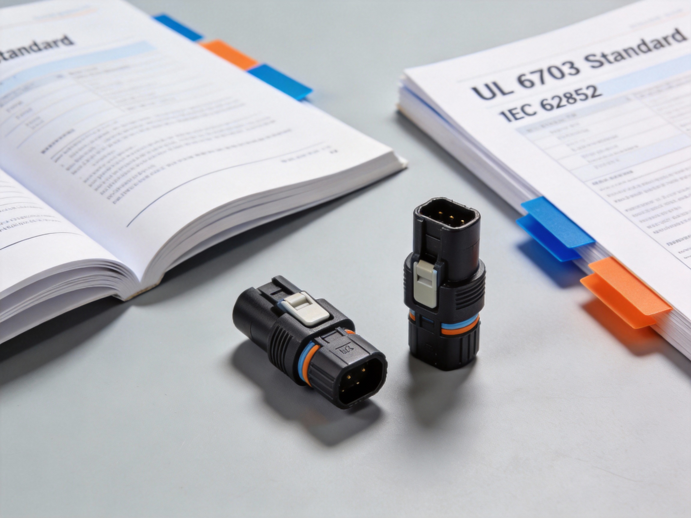
Understanding the UL 6703 Standard for Connector Safety
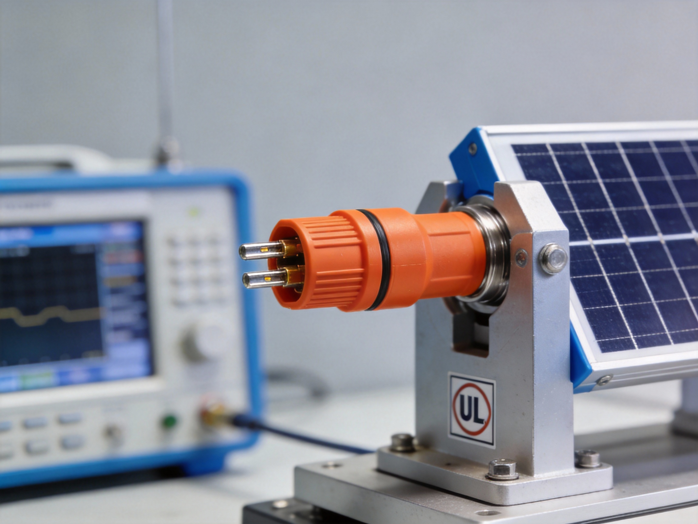
For solar installations in North America, safety certification is non-negotiable. The UL 6703 standard is the critical benchmark for solar panel connectors, specifically addressing the safety of connector systems used in photovoltaic arrays. This standard ensures that connectors can withstand the demanding electrical and environmental conditions of solar power generation, mitigating risks like fire and electric shock.
1. Scope and Purpose of UL 6703
1.1 Defining the Standard's Focus
UL 6703, formally titled "Standard for Connectors for Use in Photovoltaic Systems," applies to UL listed connectors designed for interconnecting modules, combiners, and inverters. Its primary purpose is to evaluate the safety of the connector system itself, including its housings, contacts, and locking mechanisms, under both normal and fault conditions. This focus is distinct from cable standards, ensuring the connection point is robust.
The standard covers connectors rated for system voltages up to 1500V DC and 200A, reflecting the high-power demands of modern solar arrays. It mandates testing for electrical, mechanical, and environmental durability.
1.2 The UL Mark and Market Authority
Earning the UL Listing mark signifies that a product sample has passed rigorous testing against the UL 6703 requirements. In the US and Canadian markets, this mark is a key indicator of compliance with nationally recognized safety standards. Authorities Having Jurisdiction (AHJs) and installers rely on it for verification.
"UL Standards are developed using a transparent, consensus-based process that engages a broad range of stakeholders, including manufacturers, users, and regulatory officials." — UL Solutions documentation.
2. Key Testing Criteria and Requirements
2.1 Core Electrical and Mechanical Tests
UL 6703 subjects connectors to a battery of tests simulating decades of field use. Key electrical tests include temperature rise evaluation to prevent overheating and high-current fault tests. A critical mechanical requirement is the pull-out force test, ensuring mated connectors resist accidental disconnection under tension, a common cause of arcing faults.
Connectors must also pass a dielectric voltage-withstand test at 6000V AC for one minute, verifying insulation integrity. These tests collectively ensure long-term, safe electrical performance.
2.2 Environmental and Durability Validation
To withstand outdoor exposure, connectors undergo severe environmental stress testing. This includes thermal cycling between -40°C to 85°C and damp heat testing at 85°C/85% relative humidity for 1000 hours. The salt fog corrosion test further validates material resilience in coastal environments.
Pro Tip: FR-CABLE's engineering team emphasizes that for long-term reliability, specifiers should look beyond basic UL 6703 compliance. Connectors that exceed the standard's minimum cycle counts for mating/unmating offer greater durability, especially for maintenance-heavy systems.
3. Critical Test Criteria Overview
3.1 Summarizing Major Test Parameters
The table below outlines some of the pivotal test criteria mandated by UL 6703. These parameters are essential for evaluating connector safety and longevity in real-world solar applications.
Test Category | Key Parameter | Purpose |
Electrical | Dielectric Withstand (6000V AC) | Verifies insulation won't break down under high voltage. |
Mechanical | Connector Pull-Out Force (≥ 310 N) | Ensures connection integrity against physical strain. |
Environmental | Thermal Cycling (-40°C to +85°C) | Assesses material stability across extreme temperatures. |
Durability | Mating/Unmating Cycles (≥ 30 cycles) | Tests connector lifespan for maintenance operations. |
3.2 Importance for System Safety
Compliance with these test criteria directly prevents common failure modes in solar farms. A connector failing the pull-out test could disconnect under wind load, creating a dangerous DC arc flash hazard. Similarly, failing thermal cycling can lead to cracked housings and water ingress, causing ground faults or corrosion.
Therefore, specifying UL 6703 listed connectors is a fundamental risk mitigation strategy. It provides a verified baseline for safety, protecting both the electrical system and the installation personnel.
Ultimately, understanding UL 6703 empowers stakeholders to make informed decisions, ensuring the backbone of any PV system—the interconnections—is built for safety and performance.
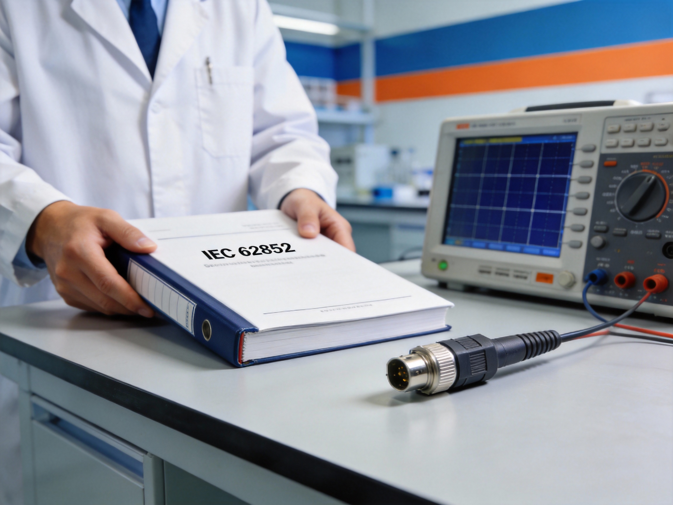
A Guide to the IEC 62852 International Standard
For solar installers and engineers operating in the global market, understanding the IEC 62852 standard is crucial for specifying and deploying safe, reliable photovoltaic (PV) systems. This international standard governs the safety, performance, and durability of connectors used in DC circuits for solar applications. While the US market is familiar with UL 6703, IEC 62852 offers a globally recognized framework with a distinct testing philosophy.
1. The Global Scope of IEC 62852
1.1 International Recognition and Applicability
IEC 62852 is the primary international safety standard for solar panel connectors in DC applications up to 1500V. It is widely adopted across Europe, Asia, Australia, and many other regions outside North America. This global acceptance makes it essential for manufacturers and system integrators whose products are deployed internationally.
Compliance with this standard is often a mandatory requirement for project financing, insurance, and grid connection in these markets. It provides a common technical language that facilitates international trade and ensures a baseline level of safety.
1.2 Core Safety Philosophy
The standard's philosophy centers on ensuring connector safety under both normal and abnormal operating conditions. It mandates that connectors must be touch-safe, preventing accidental contact with live parts. A key requirement is that connectors must be polarized or keyed to prevent mismating of positive and negative poles, a critical safeguard against reverse polarity.
This design-centric approach aims to eliminate installation errors at the source. It also requires clear, permanent marking for voltage and current ratings to inform proper system design and maintenance.
2. Key Testing Sequences and Requirements
2.1 Comprehensive Environmental and Mechanical Testing
IEC 62852 subjects connectors to a rigorous battery of tests that simulate decades of field exposure. The sequence evaluates long-term performance under harsh environmental stress. Key tests mandated by clauses like IEC 62852 Clause 12 include thermal cycling, damp heat exposure, and UV resistance assessments.
Mechanical tests, such as insertion/withdrawal force and cable pull-out resistance, ensure physical durability. The standard also includes a specific 1008-hour damp heat test at 85°C and 85% relative humidity to assess material stability and insulation integrity over time.
2.2 Electrical Safety and Fire Hazard Tests
Beyond environmental tests, the standard includes critical electrical safety evaluations. These tests verify that connectors can safely handle their rated current without overheating. A crucial sequence is the "heat rise" test, which measures temperature increase under load to prevent insulation degradation.
To mitigate fire risk, the standard includes a glow-wire test (referencing IEC 60695-2-11) to assess the flammability of insulating materials. Connectors must also pass high-current fault tests to ensure they do not become a hazard during short-circuit events.
Pro Tip: When reviewing IEC connector certification reports, the team at FR-CABLE advises paying close attention to the test results for Clause 14 (Resistance to heat and fire) and Clause 17 (Resistance to arcing). These are strong indicators of long-term field reliability under fault conditions.
3. Contrasting IEC 62852 with UL 6703
3.1 Philosophical and Testing Approach Differences
While both standards aim for connector safety, their core philosophies differ. UL 6703, as a US standard, often incorporates a prescriptive approach with specific construction requirements. In contrast, IEC 62852 is more performance-based, defining the required outcomes and safety levels while allowing more flexibility in design and material choice to achieve them.
This leads to differences in test sequences. For instance, UL 6703 includes specific tests for exposure to photovoltaic fluids, while IEC 62852 places a heavier emphasis on long-term damp heat endurance as a universal stressor.
3.2 Direct Comparison of Key Elements
The table below highlights some fundamental differences between the two standards for solar panel connectors.
Element | UL 6703 | IEC 62852 |
Core Philosophy | More prescriptive on construction | More performance-based |
Key Environmental Test | PV Fluid Exposure | 1008-hr Damp Heat (85°C/85% RH) |
Fault Current Test | Required | Required |
Primary Market | North America | International (ex-North America) |
For global projects, connectors certified to both standards offer the highest level of market acceptance and safety assurance. Understanding IEC 62852 is therefore indispensable for any professional involved in the international solar industry.
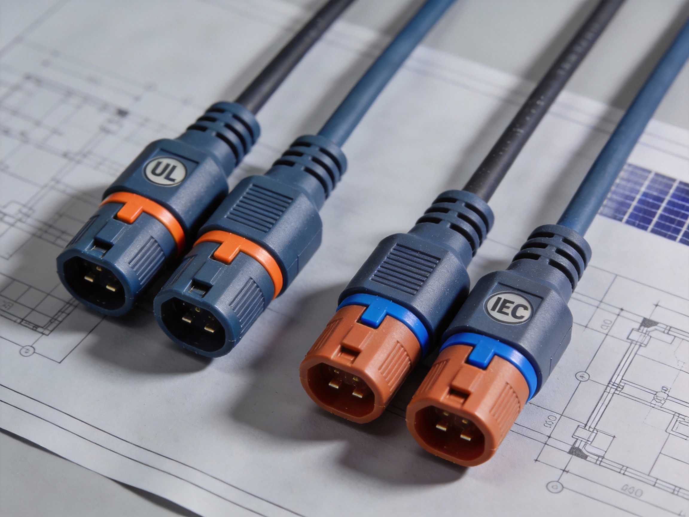
UL 6703 vs. IEC 62852: Key Differences and Similarities
For solar installers and project developers, navigating the landscape of solar connector standards is crucial for compliance and safety. The two primary standards, UL 6703 and IEC 62852, govern the performance of solar panel connectors but stem from different regulatory philosophies. This analysis breaks down their key distinctions and overlaps to clarify which standard applies to your project.
1. Core Testing and Performance Criteria
1.1 UL 6703: The North American Benchmark
UL 6703 is the U.S. and Canadian standard, focusing on durability and long-term safety in diverse environmental conditions. Its testing regimen is rigorous, emphasizing resistance to UV exposure, moisture ingress, and thermal cycling. A key requirement is the 1000-hour damp heat test at 85°C and 85% relative humidity, simulating decades of field exposure.
This standard mandates specific mechanical tests for coupling and uncoupling forces, ensuring connectors withstand physical stress during installation and maintenance.
1.2 IEC 62852: The Global Framework
IEC 62852 is the international standard, widely adopted in Europe, Asia, and other global markets. It provides a comprehensive framework for safety and functionality. While it also includes damp heat testing, the duration is typically 1000 hours at 85°C/85% RH or 300 hours at 95°C/95% RH, offering alternative compliance paths.
The IEC standard places significant emphasis on touch protection and clear marking for voltage and current ratings, aligning with global safety directives.
2. Regional Application and Market Access
2.1 Geographic Dominance and Compliance
Market access is the most practical differentiator. UL 6703 certification is essentially mandatory for any solar installation in the United States and Canada to meet National Electrical Code (NEC) and local Authority Having Jurisdiction (AHJ) requirements.
Conversely, IEC 62852 is the passport for projects in the European Union, Australia, and most Asian and Middle Eastern markets. Many manufacturers pursue dual certification to serve global supply chains efficiently.
Pro Tip: For US-based projects, FR-CABLE always advises verifying the UL 6703 listing mark on connectors. This is non-negotiable for passing inspection and ensuring system longevity under North American climatic stresses.
2.2 Choosing the Right Standard
Your project location dictates the primary standard. For US market installations, UL 6703 is not optional. For export-oriented products or international portfolios, IEC 62852 is critical.
UL 6703: Mandatory for USA/Canada, aligns with NEC, focuses on long-term environmental durability.
IEC 62852: Required for EU and many global markets, aligns with IEC system, emphasizes touch safety and clear marking.
Dual Certification: Ideal for manufacturers selling worldwide, though it involves two separate testing and audit processes.
3. Direct Comparison and Key Takeaways
3.1 Side-by-Side Analysis
The table below summarizes the critical differences between these two pivotal standards for solar connector standards comparison.
Parameter | UL 6703 | IEC 62852 |
Primary Region | United States, Canada | European Union, Global (excl. NA) |
Key Test Focus | 1000h Damp Heat (85°C/85% RH), UV, Mechanical Stress | Damp Heat (85/85 or 95/95), Touch Protection, Marking |
Governing Code | National Electrical Code (NEC) | Various National adoptions of IEC standards |
Certification Body | UL Solutions (or NRTL) | Various (TÜV, DEKRA, etc.) |
3.2 Pros and Cons Overview
Each standard has strengths shaped by its regional regulatory environment. Understanding these helps in selecting components and planning projects.
UL 6703 Pros: NEC compliance for US, rigorous environmental testing, high AHJ recognition.
UL 6703 Cons: Primarily regional, can limit component sourcing options.
IEC 62852 Pros: Global acceptance, flexible testing paths, integrated into international safety schemes.
IEC 62852 Cons: Not sufficient for US code compliance, may have less focus on specific long-term UV tests.
In summary, the choice is geographically determined. For safety and compliance, always specify the standard that aligns with your project's location and local electrical codes.
How to Identify Certified and Compatible Connectors
Selecting the correct solar panel connectors is a critical step that directly impacts system safety and performance. This guide provides a clear, step-by-step method to verify certifications and ensure mechanical and electrical compatibility, helping you avoid costly and dangerous mismatches.
1. Deciphering Connector Labels and Certifications
1.1 Locating and Reading the Markings
Every certified connector body is laser-etched or molded with crucial information. Look for the manufacturer's name or logo, the specific connector series (e.g., MC4, MC4-Evo), and most importantly, the certification marks. These markings are typically found on the connector's main housing and are your first line of verification.
Under U.S. standards, the UL 6703 certification is paramount for connector recognition. Connectors certified to this standard have undergone rigorous testing for electrical safety, durability, and environmental resistance, ensuring they meet North American market requirements.
1.2 Understanding Key Certification Marks
Certification marks are not just logos; they are legal indicators of tested compliance. The UL Listed mark confirms the product meets UL 6703. For international projects, the TÜV Rheinland mark for IEC 62852 is also a key indicator of quality and safety.
Pro Tip: FR-CABLE's technical team advises that a genuine UL mark will always be accompanied by a control number. You can verify this number on the UL Product iQ database to confirm the certification's authenticity and scope.
2. Ensuring Mechanical and Electrical Compatibility
2.1 Performing a Physical Fit Check
Certification alone does not guarantee a proper fit between different brands. Always conduct a hands-on test by fully mating a male and female connector from the kits you plan to use. A compatible pair will click securely together with a distinct, audible sound and show no visible gaps or wobble.
Forced mating or a loose connection are immediate red flags. Incompatible connectors can lead to increased resistance, overheating, and ultimately, connection failure or fire.
2.2 Verifying Electrical Specifications
Mechanical fit must be paired with electrical compatibility. Check that both connectors are rated for the same maximum system voltage (e.g., 1000V or 1500V DC) and current (e.g., 30A). Using a connector rated below your system's amperage is a severe safety hazard.
Refer to the manufacturer's datasheet for the exact specifications. A simple compatibility chart for your reference:
Voltage Rating: Must meet or exceed system max voltage
Current Rating: Must meet or exceed system max current
Conductor Size: Must match cable cross-section (e.g., 4mm² to 10mm²)
IP Rating: Should be IP67 or IP68 for weather resistance
3. Critical Warnings for Mismatched Connectors
3.1 Immediate Risks of Incompatibility
Using mismatched or uncertified connectors introduces direct, measurable risks. The primary danger is arcing and overheating at the contact point due to a poor electrical connection, which can degrade insulation and ignite surrounding materials.
This condition also leads to significant power loss—a poor connection can result in a voltage drop that reduces energy yield by 2-5% or more on a string level, directly impacting your return on investment.
3.2 Long-Term System Consequences
The long-term effects are equally severe. Moisture ingress due to an imperfect seal will cause corrosion, permanently increasing resistance. This creates a hot spot that accelerates material degradation in a feedback loop, leading to premature failure.
Such failures often void system warranties and can make insurance claims difficult. Always insist on using fully compatible, certified connector pairs from the same product line or verified interoperable brands.
By methodically applying these verification steps, you ensure a safe, efficient, and reliable photovoltaic system. When in doubt, consult technical datasheets or seek advice from qualified engineers.
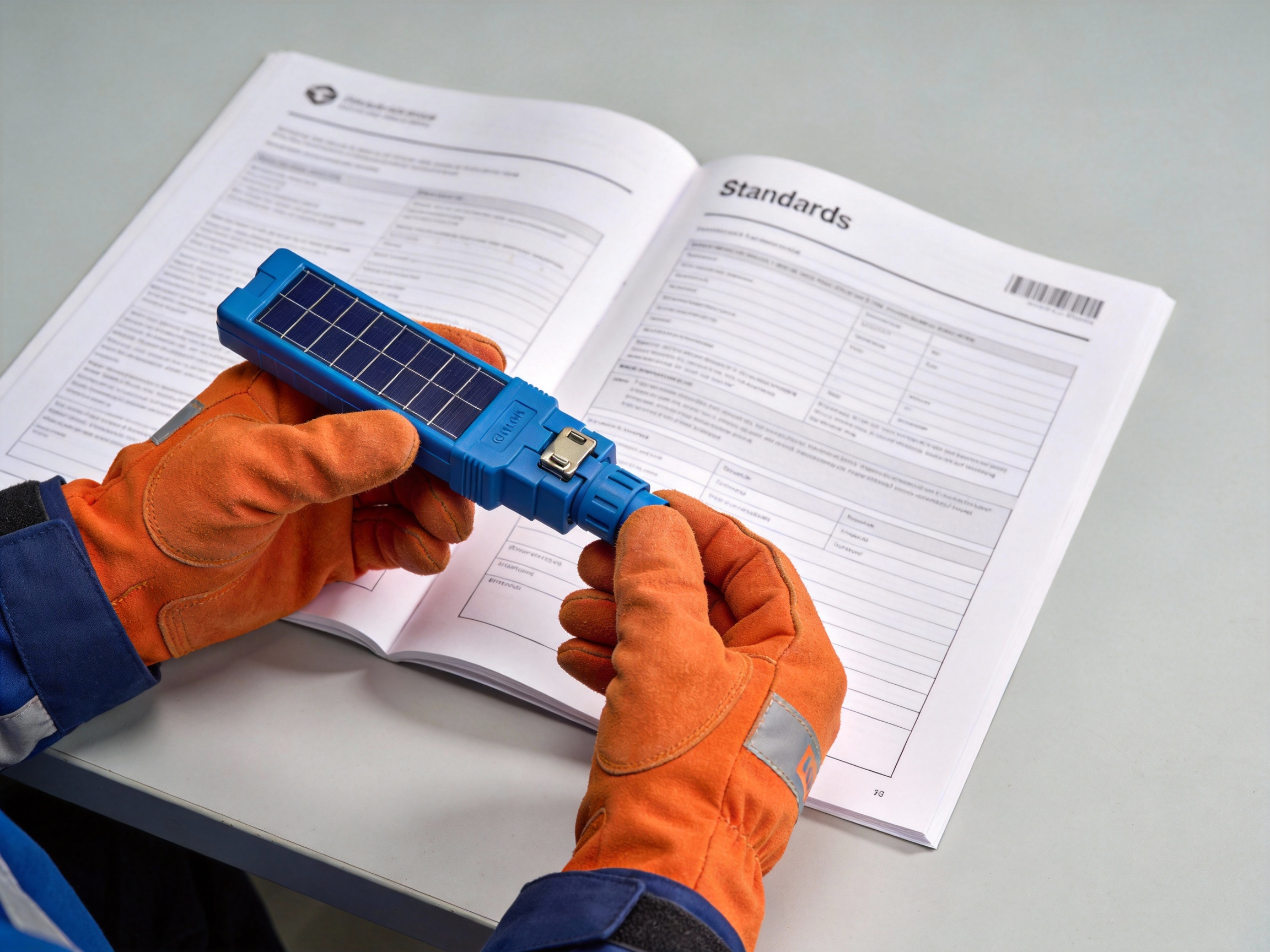
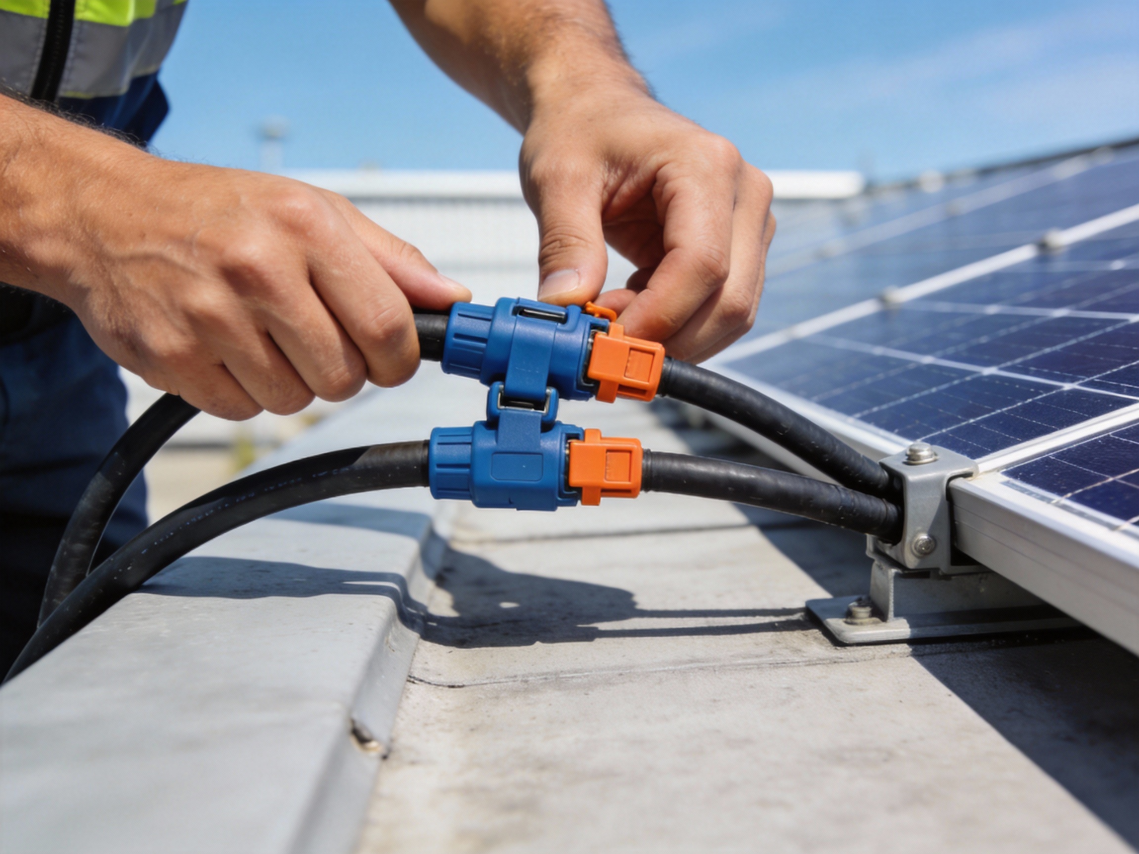
Proper Installation Techniques for Maximum Safety
A secure solar array starts with reliable connections. Improperly installed solar panel connectors are a leading cause of system failures, posing risks from energy loss to fire. This guide details the correct procedures for assembly, tool use, and inspection to ensure every connection meets the stringent requirements of standards like UL 6703 and IEC 62852.
1. Preparation and Tool Selection
1.1 Essential Tools for the Job
Using the correct solar connector crimping tool is non-negotiable for a gas-tight, low-resistance connection. A ratcheting, manufacturer-specific tool ensures consistent crimp depth and force. For field work, a professional-grade multimeter is essential for post-installation verification.
FR-CABLE technicians always verify tool calibration before starting a project, as even minor wear can compromise crimp quality. The right tooling directly impacts long-term conductivity and corrosion resistance.
1.2 Pre-Installation Inspection
Before crimping, inspect both the cable and connector for defects. Check the cable conductor for nicks or oxidation, and ensure the connector housing is free of cracks or debris. Confirm the connector series (e.g., MC4, MC4-Evo) matches the panel's junction box.
Verify cable gauge is within connector specifications
Inspect insulation for cuts or abrasions
Ensure connector seals and locking clips are present and undamaged
2. Step-by-Step Crimping Procedure
2.1 Stripping and Insertion
Strip the cable insulation to the exact length specified by the connector manufacturer, typically between 8-10 mm. An imprecise strip can leave exposed wire or prevent full conductor insertion. Insert the conductor fully into the metal contact until it bottoms out, with no strands visible at the inspection window.
2.2 Executing the Perfect Crimp
Place the contact and cable into the properly sized die of your ratcheting crimp tool. Apply steady pressure until the tool ratchet releases completely; do not release early. A proper crimp will have symmetrical indents and the wire will be immovable when gently pulled.
Pro Tip: FR-CABLE's field manual recommends performing a pull test on a sample crimp before production work. A properly crimped contact should withstand over 200 Newtons (45 lbs) of force without the conductor dislodging.
3. Final Assembly and Verification
3.1 Housing Assembly and Sealing
After crimping, route the cable through the rubber seal and housing. Push the metal contact into the housing until it clicks securely into place. Ensure the seal is seated evenly to create a waterproof barrier, a critical step for long-term reliability in outdoor environments.
3.2 Electrical and Mechanical Inspection
Use a multimeter to perform a continuity test and measure the millivolt drop across the completed connection. A voltage drop exceeding 5 mV per 10A may indicate a poor crimp. Finally, secure cables with strain relief clips to prevent tension on the connector body, which is a common failure point.
Visually compare your work to reference photos. A proper crimp has clean, centered tool marks, while an improper one may show misaligned, shallow, or over-compressed indents that compromise integrity.
Common Solar Panel Connector Failures and How to Prevent Them
Reliable electrical connections are the lifeline of any solar array. While solar panel connectors are designed for durability, real-world conditions can lead to specific failure modes that compromise system safety and performance. Understanding these common issues—from connector overheating causes to environmental degradation—and implementing preventive strategies is crucial for long-term energy yield and fire safety.

1. Primary Failure Modes and Their Root Causes
1.1 Overheating and Arcing
Overheating in solar connectors often stems from high-resistance connections created by improper installation or material fatigue. This resistance converts electrical energy into heat, which can degrade insulation and, in severe cases, lead to electrical arcing. A study by the National Renewable Energy Laboratory (NREL) noted that loose connections are a leading contributor to PV system underperformance and fire risk.
Common causes include insufficient crimping torque, incompatible connector mating, and thermal cycling stress over time, which loosens contacts.
1.2 Corrosion and Environmental Degradation
Corrosion occurs when moisture and contaminants infiltrate the connector housing, attacking the metal contacts. This increases resistance and can lead to complete connection failure. Environments with high salinity, humidity, or industrial pollution accelerate this process.
Using connectors with an IP68 rating for submersion protection is a baseline defense. However, chemical corrosion from specific atmospheric pollutants requires materials rated for that exposure.
Pro Tip: The technical team at FR-CABLE emphasizes that for coastal installations, specifying connectors with gold-plated contacts and halogen-free, UV-stabilized housings can prevent up to 90% of corrosion-related failures seen in standard components.
2. Preventive Measures and Best Practices
2.1 Adherence to Installation Standards
Strict compliance with manufacturer specifications and industry standards like UL 6703 and IEC 62852 is the first line of defense. This ensures connectors are used within their rated electrical and environmental limits.
Key installation practices include using calibrated torque tools for crimping, verifying mating audibility ("click"), and implementing proper strain relief to prevent mechanical stress on the electrical joint.
2.2 Proactive Inspection and Maintenance
A scheduled maintenance program is essential to catch failures before they cause downtime. Infrared thermography is a powerful tool for identifying hotspots indicating high-resistance connections during system operation.
A basic visual and electrical inspection checklist should include:
Checking for cracked, melted, or discolored connector housings
Verifying secure locking mechanisms and the absence of pull-out
Measuring connection resistance during periodic maintenance
Ensuring cable glands and seals are intact and weatherproof
3. Case Study Reference and Key Takeaways
3.1 Learning from a Real-World Incident
A documented case from a large-scale utility plant in Arizona highlights systemic risk. An array string experienced a 15% power loss traced to multiple connectors. Investigation revealed a combination of factors: incompatible connectors from different brands were force-mated, and thermal cycling in the desert climate exacerbated the poor contact.
The resulting micro-arcs created enough heat to melt adjacent module backsheets, creating a significant fire hazard that was caught during a routine thermal scan.
3.2 Summary of Preventive Actions
The table below consolidates the critical failure modes with targeted preventive strategies.
Failure Mode | Primary Cause | Preventive Action |
Overheating & Arcing | Loose/corroded contacts; High resistance | Use calibrated tools; Annual thermal imaging |
Corrosion | Moisture/contaminant ingress | Specify IP68+ rated, chemically resistant connectors |
Mechanical Failure | Strain, UV degradation, improper mating | Ensure full mating "click"; Provide strain relief |
Ultimately, preventing connector failures hinges on quality components, certified installation, and vigilant maintenance—a disciplined approach that safeguards both system investment and safety.
Are MC4 Connectors UL 6703 and IEC 62852 Compliant?
This is a critical question for any US solar installer. The direct answer is: MC4 is a brand name, not a certification. A connector can be an MC4-type design and also be independently certified to UL 6703 and/or IEC 62852. Compliance depends on the specific manufacturer and product model.
1. MC4: A Product Type, Not a Standard
1.1 The Origin of the MC4 Name
The term "MC4" originated as a product name from the company Multi-Contact (now part of Stäubli Electrical Connectors). It describes a specific, widely-copied design for a single-contact, solar panel connectors with a snap-in locking mechanism. Its popularity has made "MC4" a generic industry term for this connector style, much like "Kleenex" is for tissues.
1.2 Certification Applies to Products, Not Names
Safety standards like UL 6703 (US) and IEC 62852 (international) certify specific products from specific manufacturers. A company must submit its exact connector model for rigorous testing, including assessments for current rating, temperature cycling, and ingress protection. Simply calling a connector an "MC4" does not guarantee it meets these standards.
2. How to Verify Compliant MC4 Connectors
2.1 Look for Official Certification Marks
Always verify physical markings on the connector body or its packaging. Legitimate products certified for the North American market will have a UL Listed mark alongside the standard number (e.g., UL 6703). For global projects, look for the IEC 62852 designation. These marks are your primary evidence of compliance.
Reputable manufacturers provide easily accessible certification reports. FR-CABLE engineers always recommend requesting these documents from your supplier as a standard procurement step.
2.2 Source from Certified Manufacturers
To ensure safety and system longevity, procure connectors from manufacturers whose specific MC4-compatible models are certified. Major, reputable providers include:
Stäubli Electrical Connectors (the original MC4 maker)
Amphenol Industrial (e.g., Helios H4 series)
TE Connectivity (e.g., SOLARLOK series)
Other suppliers with verifiable UL 6703 listings
Pro Tip: Never intermix connector brands within a single string, even if they look identical. FR-CABLE's field data shows that mixing brands is a leading cause of thermal failures and can void certification warranties. Stick to one certified brand per installation.
3. Key Differences Between UL 6703 and IEC 62852
3.1 Regional Focus and Acceptance
UL 6703 is the benchmark for the US and Canada, often mandated by local building codes and inspectors. IEC 62852 is the international standard used widely in Europe, Asia, and Australia. While the core safety goals align, the test sequences and requirements have nuanced differences shaped by regional regulations.
3.2 Ensuring Project Compliance
For US market installations, UL 6703 compliance is non-negotiable. Many high-quality connectors are dual-certified to both standards, offering maximum flexibility. Always specify the required standard in your project documentation and validate the product's certification mark matches that requirement before installation begins.
Choosing the right certified connector is foundational to a safe, durable, and code-compliant solar array.
The Role of Connectors in Overall System Performance and Lifetime
While solar panels and inverters receive most of the attention, the humble solar panel connector is a critical linchpin for long-term system health. Poor connector quality or improper installation can silently erode energy yield, compromise safety, and significantly shorten the system's financial payback period by driving up operational costs.
1. Quantifying Efficiency Losses at the Connection Point
1.1 The Impact of Contact Resistance
Every electrical connection introduces a small amount of resistance, which converts precious generated power into wasted heat. In a high-quality, properly mated connector, this contact resistance is minimal, often below 0.5 milliohms. However, corrosion, loose crimps, or incompatible components can cause this value to spike.
For example, a resistance increase of just 5 milliohms across a single string can lead to a measurable power loss of over 1% for that circuit, directly impacting the system's annual energy production (AEP).
1.2 Cumulative Degradation Over Time
Connector performance is not static; it degrades due to environmental stress. Thermal cycling from daily temperature swings, UV exposure, and moisture ingress can gradually increase resistance. This slow degradation is often invisible during routine inspections but has a compounding effect on PV system efficiency losses.
The graph below illustrates a typical degradation curve, where poor-quality connectors can accelerate performance drop-off, leading to a steeper decline in energy output over the system's 25+ year lifespan.
2. Connector Failures and Long-Term System Costs
2.1 From Minor Loss to Major O&M Expense
A single failing connector rarely causes a complete shutdown. Instead, it creates a hotspot, leading to underperformance and posing a fire risk. Diagnosing these intermittent, localized issues requires specialized thermal imaging and skilled labor, turning a simple component into a costly operational headache.
Pro Tip: FR-CABLE's field analysis shows that nearly 30% of unexplained system underperformance traces back to connector issues. A proactive inspection and maintenance plan focused on connection points can prevent major repairs.
2.2 The Real Cost of Downtime and Repair
The financial impact extends beyond lost kilowatt-hours. A study by the National Renewable Energy Laboratory (NREL) on solar O&M costs highlights this burden: <em>"Unplanned maintenance, often driven by component failures like faulty connectors, can cost 3-5 times more than scheduled preventative maintenance due to emergency dispatch fees and faster parts replacement."</em>
Key cost drivers from connector failures include:
Emergency technician dispatch and diagnostic time
Replacement parts and potential system rewiring
Lost revenue from extended system downtime
Potential voiding of other component warranties
Ultimately, the choice of connector is an investment in system resilience. Selecting robust, compatible components and ensuring flawless installation is the most effective strategy to maximize lifetime performance and protect your return on investment.
Future Trends: Connector Standards and Technology Evolution
The landscape of solar panel connectors is not static. As photovoltaic systems become more complex and demanding, the standards governing them and the technologies enabling them must also advance. Looking ahead, the evolution will be driven by demands for higher efficiency, smarter monitoring, and enhanced safety, pushing connectors beyond their traditional role as simple electrical junctions.
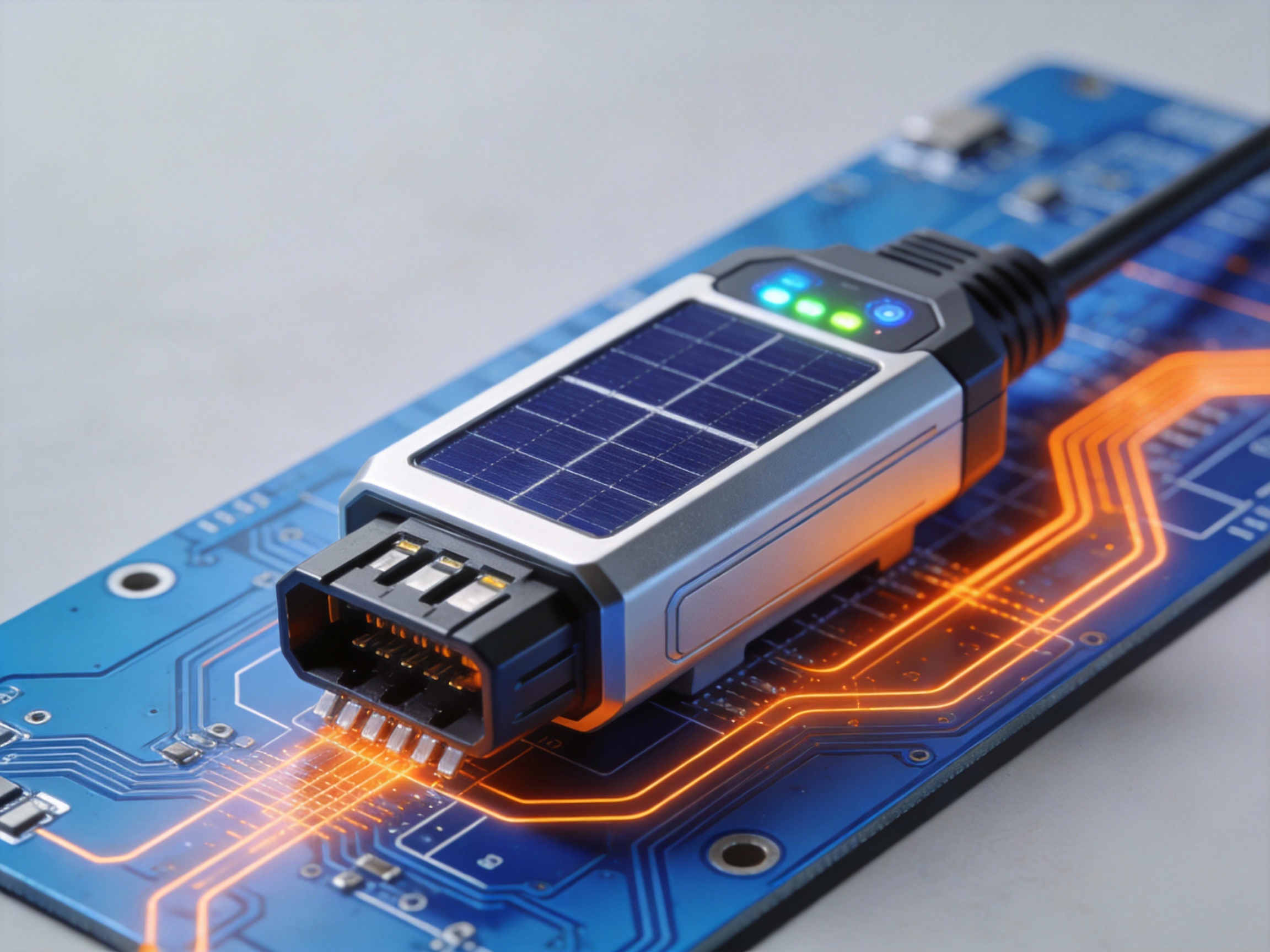
1. The Rise of Smart Connectors and Monitoring
1.1 Beyond Basic Connectivity
The next generation of solar connectors is evolving into intelligent system nodes. Smart connectors integrate sensors and microelectronics to monitor critical parameters like temperature, current, and connection integrity in real-time. This data enables predictive maintenance, helping to identify loose connections or hotspots before they lead to failures or safety hazards.
Industry analysis projects the market for such monitoring solutions in solar to grow at a CAGR of over 15% through 2030, highlighting the shift towards data-driven asset management.
1.2 Key Functions of Intelligent Systems
These advanced systems move beyond simple data collection to active system management. Core functionalities facilitated by smart interconnection points include:
Real-time performance diagnostics and anomaly alerts
Automated arc fault detection and shutdown capabilities
Energy yield optimization through module-level monitoring
Remote troubleshooting and reduced O&M site visits
2. Evolving Safety and Performance Standards
2.1 Addressing Higher System Voltages
With the industry's push towards 1500V and even 2000V DC systems to reduce balance-of-system costs, connector standards are under pressure to adapt. Future iterations of UL and IEC standards will mandate more rigorous testing for higher voltage endurance and long-term insulation resistance. This ensures connectors can safely handle the increased electrical stress over a 25+ year lifespan.
Pro Tip: FR-CABLE's R&D team emphasizes that future-proofing installations means selecting connectors rated well above today's system voltages, as upgrades are inevitable. Always consult the latest draft standards during system design.
2.2 Enhanced Durability and Environmental Testing
Climate resilience is becoming a paramount concern. Expect new standard requirements for extreme weather cycles, higher ingress protection (IP) ratings for harsh environments, and improved resistance to corrosion from salt spray or ammonia. Connectors will need to prove reliability in a wider range of temperature extremes and mechanical stress conditions.
3. Staying Ahead of the Innovation Curve
3.1 A Call for Continuous Education
For installers, designers, and asset owners, staying informed is no longer optional. The pace of technological change means that practices considered best-in-class today may be outdated in five years. Engaging with industry publications, attending trade shows, and participating in continuing education courses from manufacturers and standards bodies is crucial.
This proactive approach ensures compliance, maximizes system safety and ROI, and enables the adoption of cutting-edge solutions that boost performance.
Ultimately, the future of solar connectors lies at the intersection of robust engineering, intelligent functionality, and forward-looking standards. By understanding these trajectories, stakeholders can make informed decisions that ensure their solar investments are safe, efficient, and built to last.
