4 AWG Wire Specifications: Gauge, Amps, and Applications
- Vicky

- 3 hours ago
- 19 min read
What is 4 AWG Wire? A Complete Definition and Gauge Explanation
Understanding wire gauge is fundamental to any electrical project. The American Wire Gauge (AWG) system is the standard used in North America to define the diameter of electrical conductors. This guide explains the AWG system and the specific role of 4 AWG wire, a common size for demanding applications.
1. Defining the American Wire Gauge (AWG) System
1.1 The Core Principle
The AWG system is a logarithmic scale where a higher gauge number indicates a thinner wire. The system is based on the number of drawing operations required to reduce a wire to a specific diameter. For instance, moving from 4 AWG to 6 AWG represents a significant increase in cross-sectional area.
This inverse relationship is critical for understanding current capacity, as thicker wires (lower AWG) have less electrical resistance and can safely carry more current.
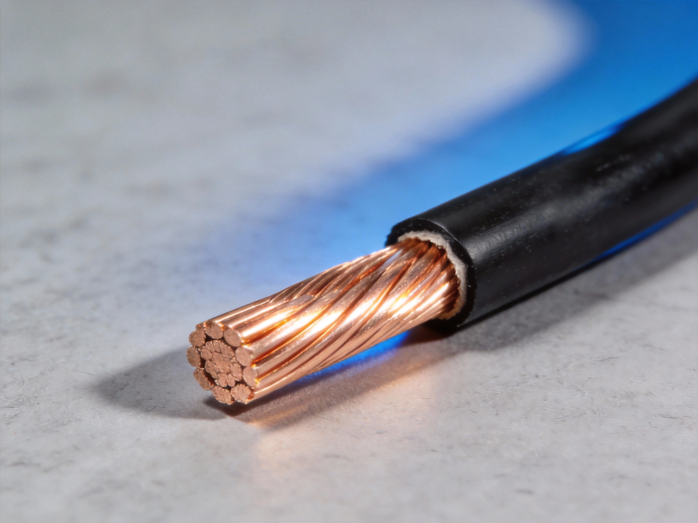
1.2 Key Parameters of 4 AWG Wire
A 4 AWG wire has a nominal diameter of approximately 0.2043 inches (5.189 mm). Its key electrical characteristic is its ability to handle high current loads, typically up to 85-95 amps for chassis wiring or 70-85 amps for power transmission, depending on insulation and installation conditions.
Nominal diameter: 0.2043 inches (5.189 mm)
Typical ampacity range: 70-95 Amps
Common insulation types: THHN, THWN-2, XHHW
Primary material: Stranded or solid copper
2. Where 4 AWG Fits on the Gauge Scale
2.1 Visualizing the Gauge Progression
To understand 4 AWG, it helps to see it within the broader spectrum of common wire sizes. It sits firmly in the range of heavy-duty conductors, larger than standard household branch circuits but smaller than the massive cables used for service entrances.
The scale below illustrates its relative position among frequently used gauges for power distribution.
2.2 Comparative AWG Sizes Table
The following table compares 4 AWG to adjacent, commonly used gauges, highlighting its role as a high-capacity conductor for specific applications.
AWG Size | Typical Max Ampacity | Common Applications |
2 AWG | ~95-115 A | Large sub-panels, welders |
4 AWG | ~70-95 A | Electric ranges, hot tubs, EV chargers |
6 AWG | ~55-75 A | Electric dryers, AC units |
8 AWG | ~40-55 A | Small sub-panels, cooktops |
Ampacity varies based on insulation type, ambient temperature, and NEC guidelines. Always consult local code.
Pro Tip: When sizing a cable for a high-amperage circuit like an EV charger, FR-CABLE engineers emphasize not just meeting the minimum ampacity but also factoring in voltage drop over long runs and future-proofing for potential load increases.
In summary, 4 AWG is a robust conductor defined by a precise diameter within the AWG system, designed to safely deliver substantial power for major appliances and equipment. Its specifications make it a cornerstone for reliable, high-current electrical installations.
4 AWG Wire Amperage Rating: How Many Amps Can It Handle?
The ampacity of a 4 AWG wire—its maximum safe current-carrying capacity—is not a single number. It depends primarily on the wire's insulation type and installation conditions. Understanding these factors is crucial for designing safe and code-compliant electrical systems.
1. Core Ampacity Based on NEC Standards
1.1 The NEC Ampacity Table Reference
The National Electrical Code (NEC) provides the definitive ampacity chart for wire sizing in the United States. For 4 AWG copper wire, the base rating varies significantly with insulation temperature rating. Common ratings include 85 amps for 60°C insulation and 95 amps for 75°C insulation.
These values assume specific installation conditions, such as an ambient temperature of 30°C (86°F) and no more than three current-carrying conductors in a raceway or cable.
1.2 Key Factors Influencing Actual Capacity
Real-world installations rarely match ideal NEC table conditions. Several critical safety factors require derating the base ampacity. Ambient temperature is a primary factor; higher temperatures reduce a wire's ability to dissipate heat.
Other derating considerations include the number of conductors bundled together and the installation method, such as in conduit versus free air. FR-CABLE engineering notes emphasize that overlooking these adjustments is a common design error leading to overheating.
2. Calculating Adjusted Ampacity
2.1 Applying Derating Factors
The formula explanation for adjusted ampacity is straightforward: multiply the NEC table value by all applicable correction factors. For example, if a 4 AWG THHN wire (95A base) is installed in a location with a 40°C ambient, you must apply a 0.91 correction factor.
This calculation yields an adjusted ampacity of approximately 86 amps. Bundling more than three conductors requires an additional multiplier, further reducing the safe current limit.
Pro Tip: Always size the overcurrent protection device (circuit breaker or fuse) based on the adjusted ampacity, not the NEC table value. FR-CABLE specialists recommend adding a final 10-20% safety margin for dynamic loads to ensure long-term reliability and prevent nuisance tripping.
2.2 Common Applications and Limits
4 AWG wire is frequently used for feeder circuits to subpanels, large appliance circuits, and some EV charger installations. Its typical ampacity range of 70-95 amps makes it suitable for 80-100 amp circuit breakers after derating.
Key applications include:
Residential 100-amp sub-panel feeders
Commercial equipment requiring high inrush current
Long branch circuit runs where voltage drop is a concern
3. Essential Reference: NEC Ampacity Table (Simplified)
3.1 Copper Conductor Comparison
The table below summarizes common ampacities for 4 AWG copper wire from NEC Table 310.16. These values are for reference; always consult the full code and apply derating.
Insulation Type | Temperature Rating | Ampacity (NEC Table) |
TW, UF | 60°C | 85 A |
THW, THWN, XHHW | 75°C | 95 A |
THHN, THWN-2 | 90°C | 105 A |
The 90°C rating (105A) is typically used for derating calculations only. The final ampacity for termination purposes is limited by the lowest temperature rating of any connected device, often 75°C.
Selecting the correct 4 AWG wire requires more than just checking a table. By understanding and applying NEC ampacity rules and derating factors, you ensure a system that is safe, efficient, and compliant.
Key Electrical Specifications: Diameter, Resistance, and Weight
For engineers and electricians, selecting the correct wire gauge is a foundational calculation that impacts safety, efficiency, and cost. The key electrical specifications—diameter, resistance, and weight—are intrinsically linked and governed by standards like the NEC. This chapter provides the essential technical data for 4 AWG wire to inform your design and installation decisions.
1. Core Specifications for 4 AWG Wire
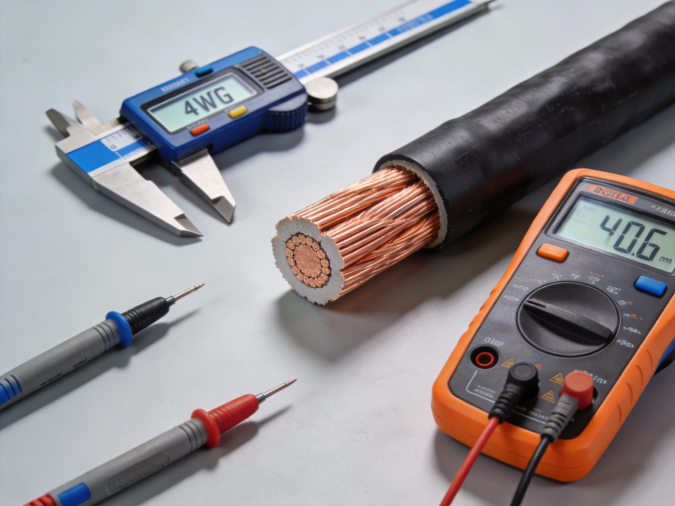
1.1 Diameter and Construction
The nominal diameter of a 4 AWG copper conductor is approximately 0.232 inches (5.89 mm), as defined by the American Wire Gauge standard. This measurement refers to the bare conductor. The overall cable diameter increases significantly with insulation, which varies by type (e.g., THHN, XHHW).
For accurate conduit fill calculations per NEC Chapter 9, always use the overall insulated diameter from the manufacturer's specifications, not the bare conductor size.
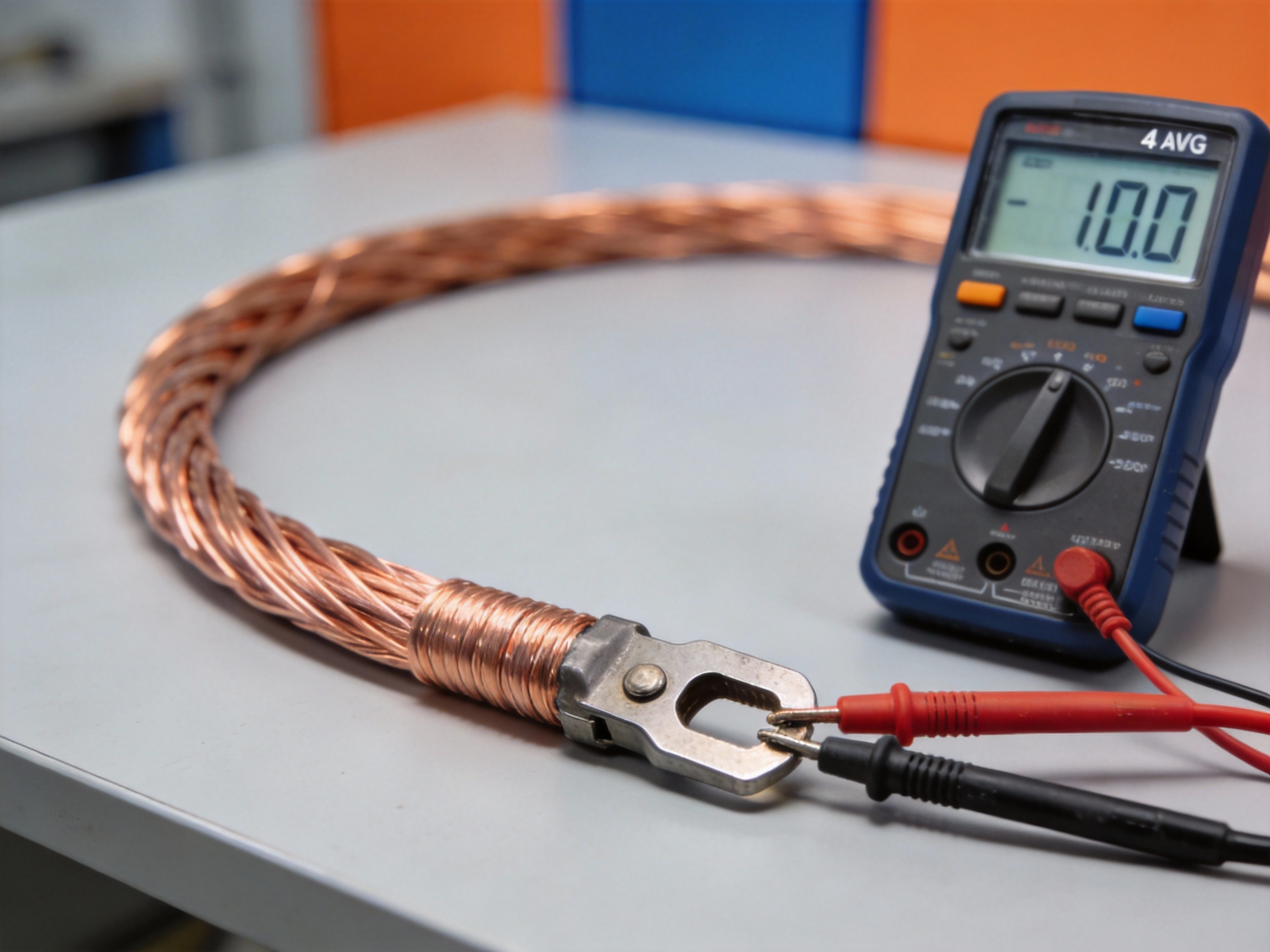
1.2 Resistance and Weight per 1000 ft
The DC resistance at 75°C is a critical parameter for voltage drop calculations. For 4 AWG copper, the standard wire resistance per 1000 ft is approximately 0.308 ohms. The corresponding weight is about 126.4 pounds per 1000 feet of bare copper.
These values are based on standard annealed copper; using copper-clad aluminum or different tempers will alter the figures. The following table summarizes the key data:
Specification | Value for 4 AWG Copper | Notes |
Bare Diameter | 0.232 in (5.89 mm) | AWG Standard |
DC Resistance @ 75°C | ~0.308 Ω/1000 ft | NEC Table 8 |
Weight | ~126.4 lb/1000 ft | Bare Conductor |
2. Comparative Analysis with Other Gauges
2.1 Performance Trade-offs
Moving from a 6 AWG to a 4 AWG wire represents a significant step up in current-carrying capacity and a reduction in resistance. The cross-sectional area nearly doubles, which directly impacts performance in three key areas:
Higher ampacity for feeder and branch circuits
Lower voltage drop over long distances
Increased mechanical strength and durability
2.2 Practical Application Context
Choosing 4 AWG over 2 AWG or 6 AWG is often a balance of cost, physical space, and electrical need. For instance, a 4 AWG THHN copper conductor has a maximum ampacity of 85 amps for most common installations (NEC Table 310.16).
Pro Tip: When calculating for long runs, FR-CABLE engineers recommend using the actual resistance value and the full load current to model voltage drop, as simply upsizing to the next gauge may not be the most cost-effective solution.
Understanding these interrelated specifications allows for precise system design that meets code, ensures safety, and optimizes performance. Always consult the latest NEC tables and manufacturer data for project-specific calculations.
Common Applications for 4 Gauge Electrical Wire
4 AWG wire is a workhorse in electrical systems, bridging the gap between standard branch circuits and massive feeder cables. Its substantial cross-sectional area allows it to handle high current loads with minimal voltage drop, making it a go-to solution for specific, demanding applications. Understanding where and why this gauge is used is crucial for safe and compliant installations, particularly when referencing standards like NEC Article 310 for conductor sizing and ampacity.
1. Residential and Commercial Power Distribution
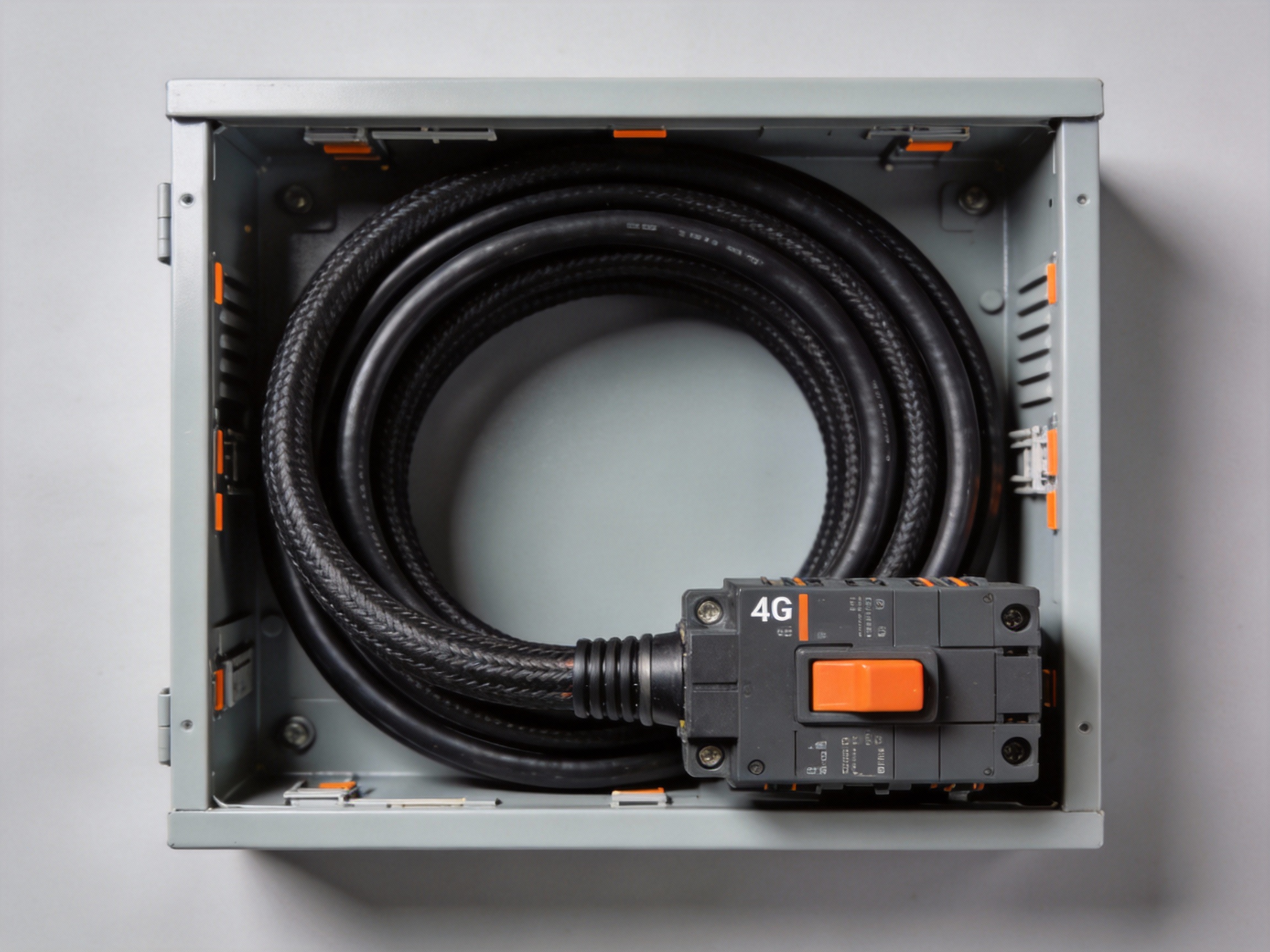
1.1 Service Entrance and Main Feeders
One of the most critical applications for 4 gauge wire is as a service entrance conductor or main feeder for sub-panels. In many residential and light commercial settings, it serves as the primary power path from the utility meter to the main service panel. For example, a 100-amp residential service often utilizes 4 AWG copper conductors, as its ampacity aligns with this common service size when installed in typical conditions.
Its use is dictated by the National Electrical Code, specifically NEC Table 310.16, which lists its ampacity. This application demands wire with robust insulation, such as THHN/THWN-2 or USE-2, to withstand environmental exposure and high continuous loads.
1.2 Large Appliance and HVAC Circuits
High-power appliances and HVAC systems frequently require the capacity of 4 AWG wire. This includes circuits for electric ranges, large tankless water heaters, and substantial air conditioning or heat pump units. The wire's ability to deliver 80-85 amps (for copper, 60°C termination rating) ensures these devices start and run efficiently without tripping breakers or causing dangerous overheating.
Common installation points include the dedicated circuit from the main panel to the appliance disconnect. Proper sizing here prevents voltage sag, which can reduce equipment performance and lifespan.
Pro Tip: When running 4 AWG for a sub-panel, FR-CABLE experts always recommend a four-wire setup (two hots, one neutral, one ground) to meet modern NEC separation requirements and ensure safety.
2. Automotive and High-Current DC Systems
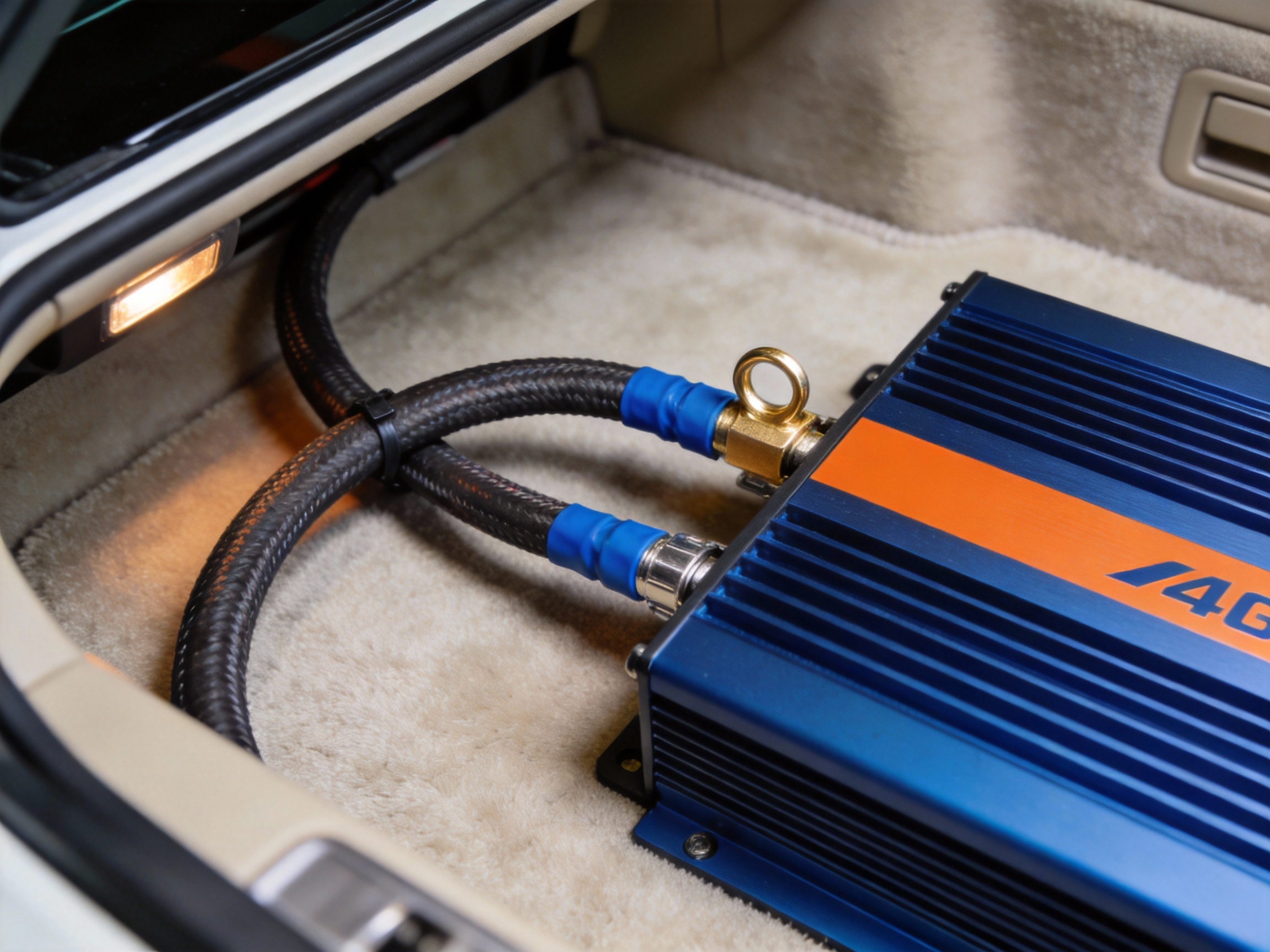
2.1 Amplifier and Audio System Wiring
In automotive audio, 4 gauge wire is the standard for main power runs from the battery to high-wattage amplifiers and distribution blocks. Its low resistance is essential for delivering the burst current needed by high-performance audio equipment without dimming lights or causing electrical interference. This application highlights the wire's role in 12V DC systems where minimizing voltage drop over distance is paramount.
Key specifications for this use include fine strand count for flexibility and high-purity copper for optimal conductivity, ensuring clear signal transmission and amplifier efficiency.
2.2 Winches, Plows, and Auxiliary Equipment
Off-road vehicles, trucks, and utility equipment use 4 AWG cable to power high-torque electric winches, snow plows, and inverters. These devices draw immense current for short durations, requiring a conductor that can handle the surge without overheating. The wire acts as a robust electrical highway, connecting the battery or auxiliary battery bank directly to the heavy-duty solenoid or control unit.
For these demanding environments, insulation with excellent abrasion, oil, and temperature resistance is non-negotiable to ensure long-term reliability and safety.
3. Key Specifications and Installation Notes
3.1 NEC Compliance and Ampacity
All applications must adhere to the ampacity ratings defined in the National Electrical Code. For 4 AWG THHN copper wire in a typical raceway or cable, the ratings are: 85A at 60°C, 95A at 75°C, and 105A at 90°C. The final usable ampacity is governed by the lowest temperature rating of any connected terminal or device, often making the 60°C column the default for residential panels.
These ratings ensure the wire operates within safe temperature limits, preventing insulation degradation and fire risk over its service life.
3.2 Common Cable Types and Selection
Choosing the right 4 AWG cable type is as important as the gauge itself. Each type is designed for specific environments and codes.
THHN/THWN-2: Versatile, dual-rated for dry and wet locations, common in conduit
XHHW-2: Excellent chemical and heat resistance, often used in commercial buildings
USE-2/RHH/RHW-2: Suitable for direct burial or service entrance applications
Welding Cable (WELD): Extremely flexible, fine-stranded for automotive and DC power
Matching the cable type to the installation environment—conduit, direct burial, or engine bay—is critical for compliance and durability.
From powering a home to energizing a winch, 4 AWG wire proves its value in high-amperage scenarios where reliability and safety cannot be compromised.
How to Choose Between 4 AWG and 2 AWG or 6 AWG Wire
Selecting the correct American Wire Gauge (AWG) is a critical decision that balances performance, safety, and cost. This guide will help you navigate the key differences between 4 AWG, 2 AWG, and 6 AWG wires, focusing on their current-carrying capacity and voltage drop characteristics for your specific application.
1. Core Specifications and Comparison
1.1 Key Physical and Electrical Properties
The AWG system is logarithmic, meaning a lower number indicates a thicker wire with less electrical resistance. For instance, a 2 AWG wire has a larger diameter and lower resistance than a 4 AWG wire, which in turn is superior to 6 AWG. This fundamental difference directly impacts their maximum current capacity (ampacity) and performance over distance.
According to the National Electrical Code (NEC), the typical ampacity for copper THHN wire in a raceway is approximately 70A for 6 AWG, 85A for 4 AWG, and 115A for 2 AWG. These values are the starting point for any sizing calculation.
1.2 Direct Comparison Table
This table provides a clear, at-a-glance comparison of the three gauges for copper conductors, based on common standards.
Wire Gauge (AWG) | Approx. Diameter (in) | Max Ampacity (Copper THHN) | Typical Use Case |
6 AWG | 0.162 | 55-70 Amps | Electric ranges, sub-panels (shorter runs) |
4 AWG | 0.204 | 70-85 Amps | Major appliances, EV chargers, 100A sub-panels |
2 AWG | 0.258 | 95-115 Amps | Service entrance cables, long feeder runs |
Ampacity varies with insulation type and installation conditions. Always consult the latest NEC tables.
2. The Decision-Making Process
2.1 Calculating Voltage Drop
Voltage drop is the reduction in voltage as current travels through a wire. For long runs, it's often the deciding factor over ampacity alone. The formula is: Voltage Drop (Vd) = 2 x Length (ft) x Current (A) x Resistance (Ω/ft).
Example: For a 50-amp load over 100 feet, 6 AWG copper may cause a ~3.2% drop, while 4 AWG reduces it to ~2.0%. Exceeding a 3% drop for branch circuits can lead to poor equipment performance, making 4 AWG the better choice here.
2.2 Application-Based Selection Guide
Use this decision framework to narrow your choice. Start with your load's amperage and the one-way circuit length.
Short runs (<50 ft) with moderate load: 6 AWG is often sufficient and cost-effective.
Standard 100A sub-panel or EV charger: 4 AWG is the typical, code-compliant choice for most distances.
Long runs (>100 ft) or high-amperage feeds: Upsize to 2 AWG to mitigate significant voltage drop.
Future-proofing or uncertain loads: Opt for the larger gauge (e.g., 2 AWG over 4 AWG) for headroom.
Pro Tip: For complex installations involving long distances or variable loads, consulting with a specialist like FR-CABLE can ensure your wire gauge selection optimizes for both safety and efficiency, preventing costly undersizing errors.
3. Practical Considerations and Best Practices
3.1 Cost vs. Performance Trade-off
While 2 AWG wire offers the best performance, it is significantly more expensive and difficult to work with than 4 AWG or 6 AWG. The thicker wire requires larger conduit and more labor to install. The key is to avoid false economy; undersizing to save upfront cost can lead to voltage drop issues, overheating, and the need for a complete rewire.
3.2 Installation and Code Compliance
Always prioritize the NEC guidelines as the absolute minimum standard. Local codes may be stricter. Key considerations include the wire's insulation rating for the environment (e.g., THHN for dry locations, THWN for wet), proper overcurrent protection at the breaker, and correct termination at lugs rated for the specific wire gauge.
For critical power infrastructure, specifying cables from a trusted manufacturer ensures consistent quality and performance data, which is vital for accurate calculations and long-term reliability.
By systematically evaluating your amperage, distance, and application needs against these specifications, you can confidently select the optimal AWG—whether it's 6, 4, or 2—for a safe and effective electrical installation.
Step-by-Step Guide: How to Properly Install 4 AWG Cable
Installing 4 AWG cable is a critical task for high-amperage circuits like EV chargers, solar inverters, or sub-panels. A proper installation ensures safety, reliability, and compliance with the National Electrical Code (NEC). This guide provides actionable steps, focusing on the correct tools and techniques for secure wire termination lugs.
1. Preparation and Safety
1.1 Required Tools and Materials
Gathering the right tools before starting is essential for a clean, professional installation. Using improper tools can damage the cable or create a weak connection.
Wire stripper rated for 4 AWG
High-quality crimping tool with correct die
Torque wrench or screwdriver
Heat gun and adhesive-lined heat shrink tubing
De-oxidizing compound for copper lugs
1.2 Mandatory Safety Precautions
Always verify the circuit is de-energized using a voltage tester before handling any wires. Wear appropriate PPE, including safety glasses and insulated gloves. Ensure your work area is dry and well-lit to prevent accidents.
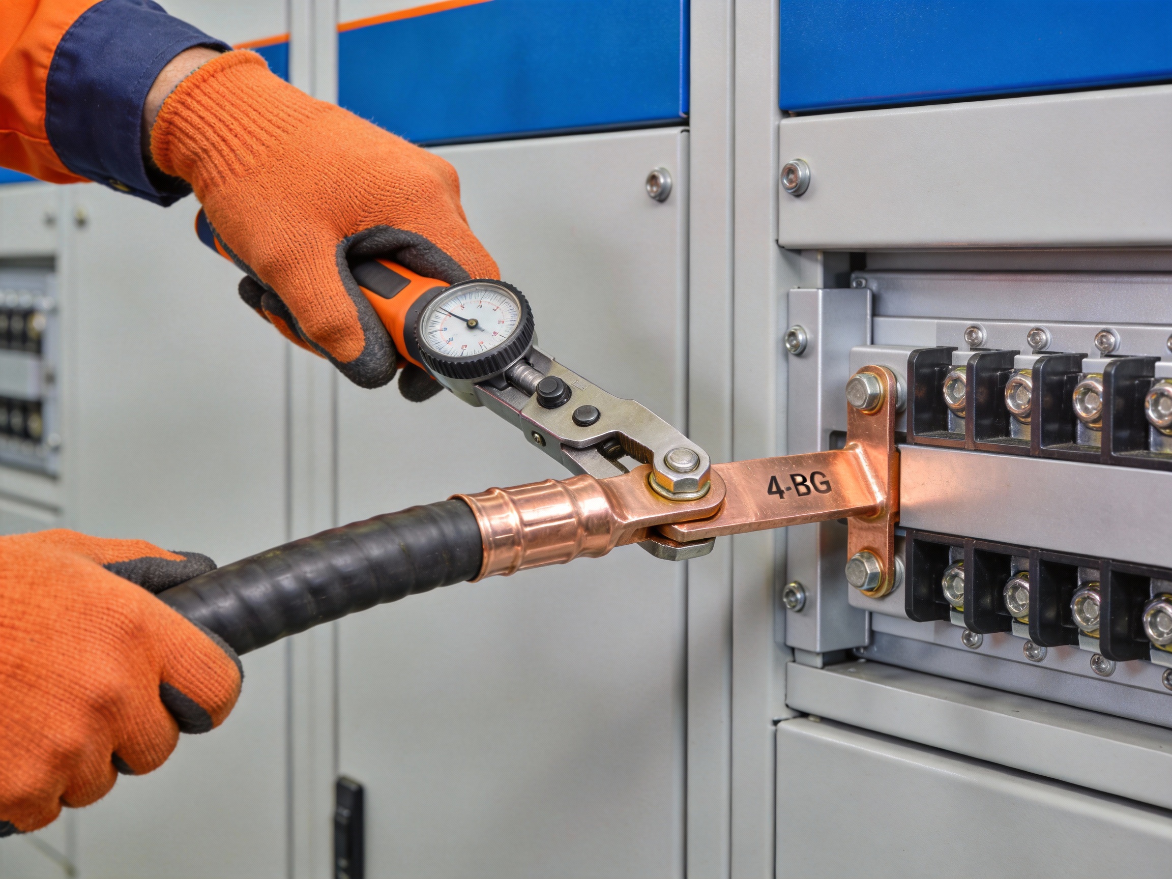
Pro Tip: FR-CABLE's technical team emphasizes that for 4 AWG installations, a calibrated torque tool is non-negotiable to achieve the manufacturer-specified connection pressure, typically between 25-35 in-lbs for common lugs.
2. Execution and Termination
2.1 Stripping and Preparing the Conductor
Measure and strip the cable jacket to expose the precise length of bare copper specified by the lug manufacturer, usually about 3/4 inch. Avoid nicking the individual strands, as this reduces current-carrying capacity. Apply a thin layer of de-oxidizing compound to prevent corrosion.
2.2 Crimping the Wire Termination Lug
Insert the prepared conductor fully into the lug barrel. Select the correct die for 4 AWG on your crimper. Position the tool and apply firm, even pressure to create a permanent, cold-weld connection. A proper crimp will be uniform and show no gaps between the lug and wire.
Incorrect crimping is a leading cause of connection failure, leading to overheating and potential fire hazards.
3. Final Connection and Verification
3.1 Securing the Connection Point
Slide adhesive-lined heat shrink tubing over the crimped joint and apply heat until it seals completely. This provides strain relief and environmental protection. Mount the lug to its terminal (e.g., breaker, bus bar) and use your torque wrench to tighten the fastener to the exact specification.
3.2 Post-Installation Inspection
Conduct a thorough visual and mechanical inspection before re-energizing the circuit. Ensure there is no exposed copper, all connections are tight, and cables are properly supported.
Verify all terminations are secure and free of debris
Check for proper cable bending radius (at least 5x cable diameter)
Confirm conductors are correctly phased and labeled
Following these steps methodically will result in a safe, code-compliant 4 AWG cable installation built for long-term performance.
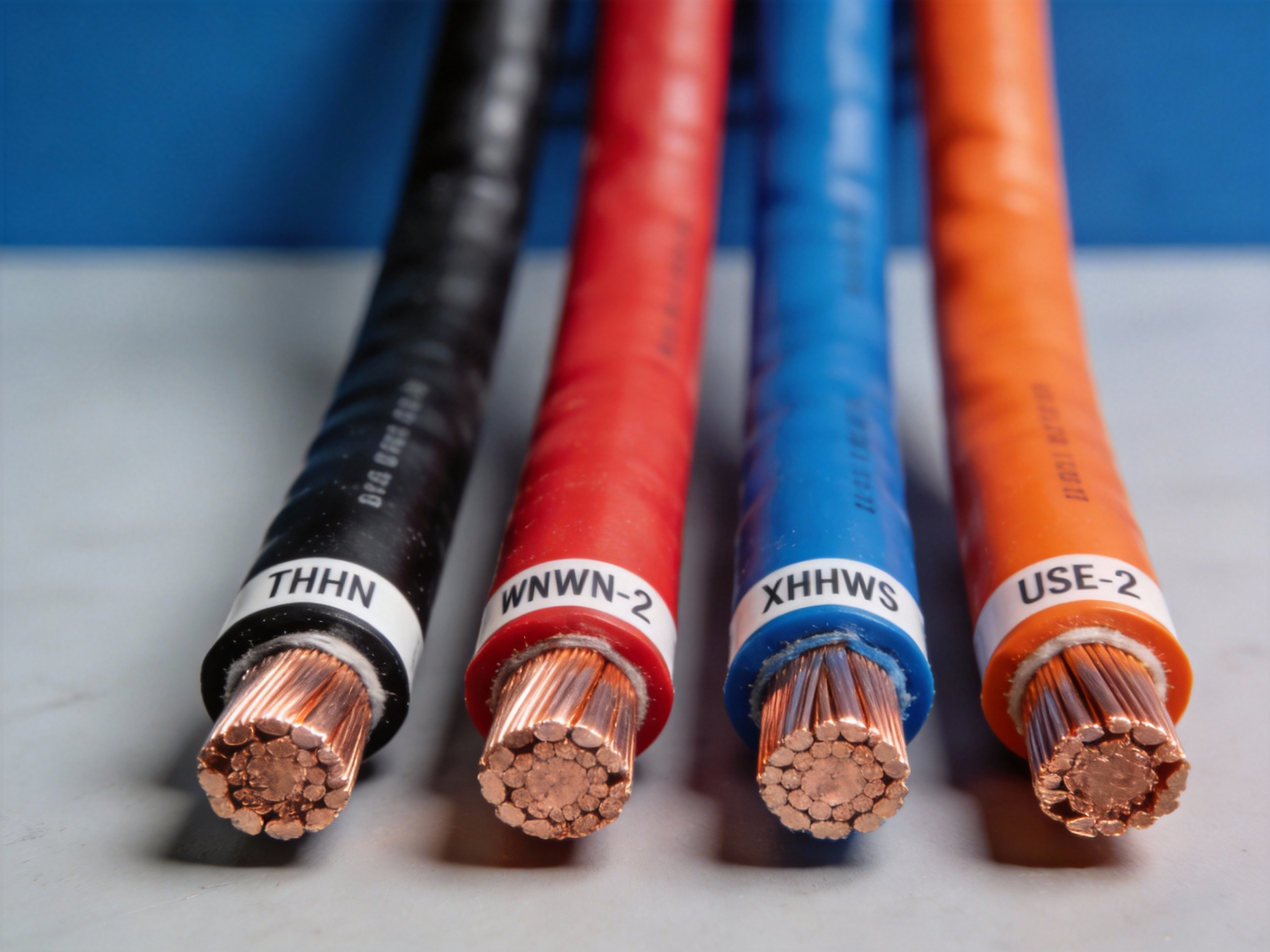
Understanding 4 AWG Wire Types: THHN, THWN-2, XHHW, and More
Selecting the correct 4 AWG wire for your project goes beyond just the conductor size. The insulation and jacket materials define its performance, safety, and lifespan in specific environments. This guide breaks down common types like THHN, THWN-2, and XHHW, explaining their ratings and ideal applications to ensure a compliant and durable installation.
1. Decoding Common Insulation Types
1.1 THHN vs. THWN-2: The Versatile Workhorse
THHN (Thermoplastic High Heat-resistant Nylon-coated) is a widely used building wire for dry, indoor locations. It is rated for up to 90°C in dry conditions and is known for its thin, slick nylon jacket that aids in pulling through conduit. THWN-2 carries all the ratings of THHN but adds a crucial "W" for water resistance, allowing it to be used in both wet and dry locations.
Essentially, modern THWN-2 wire supersedes THHN, offering broader application flexibility. It is the default choice for most general-purpose 4 AWG branch circuit and feeder installations in conduit.
1.2 XHHW: The Durable Cross-Linked Option
XHHW (Cross-linked Polyethylene High Heat-resistant Water-resistant) features a thermoset, cross-linked polyethylene (XLPE) insulation. This material offers superior resistance to heat, moisture, and abrasion compared to standard thermoplastic. XHHW is typically rated for 90°C in both wet and dry locations.
Its thicker, tougher construction makes it excellent for harsh environments, direct burial (when specified), and applications where long-term thermal stability is a priority. It is a common choice for service entrance conductors and industrial power distribution.
Pro Tip: When in doubt between THHN and XHHW for a demanding environment, the team at FR-CABLE often recommends XHHW for its enhanced durability and thermal aging characteristics, which can extend the cable's service life.
2. Environmental Ratings and Application Suitability
2.1 Wet vs. Dry Location Ratings
The "W" in a wire's designation is critical. A wire rated for wet locations can be installed in areas exposed to moisture, direct burial (with appropriate protection), or in concrete slabs. Dry location wires, like basic THHN, are restricted to indoor areas not subject to dampness.
For 4 AWG wiring in conduits that may condense moisture or run outdoors, always specify a wet-rated type like THWN-2 or XHHW to prevent insulation degradation and safety hazards.
2.2 Temperature Ratings and Ampacity
A wire's temperature rating (e.g., 75°C, 90°C) indicates the maximum temperature its insulation can withstand without degrading. This rating directly impacts the wire's ampacity—its current-carrying capacity. A 4 AWG copper THWN-2 conductor, for instance, has an ampacity of 85 amps at the common 75°C termination rating.
Always match the wire's temperature rating to the lowest-rated component in the circuit (e.g., breaker terminals) to ensure safe operation and compliance with the National Electrical Code (NEC).
3. Insulation Comparison and Selection Guide
The table below summarizes key characteristics to aid in selecting the right 4 AWG wire type for your application.
Type | Insulation Material | Max Temp (Dry/Wet) | Key Features & Best For |
THHN | Thermoplastic (PVC) + Nylon | 90°C / Not Rated | Cost-effective; dry, indoor conduit only. |
THWN-2 | Thermoplastic (PVC) + Nylon | 90°C / 75°C or 90°C | Versatile; wet/dry locations; general conduit use. |
XHHW | Cross-linked Polyethylene (XLPE) | 90°C / 90°C | Durable, heat/moisture resistant; harsh environments, direct burial. |
USE-2/RHH/RHW-2 | Cross-linked Polyethylene (XLPE) | 90°C / 90°C | High-temp service; underground service entrance (USE-2). |
Varies by manufacturer. When specifically listed for direct burial.
Understanding these distinctions ensures your 4 AWG installation is not only code-compliant but also optimized for performance and longevity in its specific operating environment.
4 AWG Wire for Car Audio: Is It the Right Choice for Your Amp?
Choosing the correct car audio power wire is critical for performance and safety. This guide dives into the specifics of 4 AWG wire, helping you determine if it matches your amplifier's demands and outlining key installation considerations.
1. Determining Your Power Requirements
1.1 Calculating Total Current Draw
Start by calculating your amplifier's maximum current draw. Use this formula: Total RMS Wattage / System Voltage (typically 13.8V) = Approximate Amperage. For a 1000W RMS system, that's roughly 72.5 amps.
This calculation is essential for selecting a wire gauge that can handle the load without excessive voltage drop, which starves your amp of power.
1.2 The 4 AWG Wire Capacity
4 AWG wire is a common choice for mid-to-high-power systems. It can typically handle up to 150 amps for runs under 17 feet in a standard car audio environment.
Consider the total length from battery to amp and back. Longer runs increase resistance, requiring a thicker gauge to maintain voltage. A simple power requirement calculator should factor in this distance.
2. Installation and Safety Essentials
2.1 Fuse Sizing Guide
Proper fusing protects your vehicle from fire. The fuse rating should match or be slightly lower than the wire's maximum amperage capacity, not the amplifier's draw.
Place a fuse within 18 inches of the battery's positive terminal
Use an ANL or AGU style fuse holder for 4 AWG wire
For a 4 AWG kit rated for 150A, use a 125A or 150A fuse
2.2 Material Quality: OFHC vs. CCA
Wire material drastically affects performance. Oxygen-Free High Conductivity (OFHC) copper offers superior conductivity and flexibility compared to Copper-Clad Aluminum (CCA).
CCA wire has higher resistance, meaning a 4 AWG CCA wire may perform like a thinner OFHC copper wire, leading to power loss and potential overheating under heavy load.
Pro Tip: For high-current applications, FR-CABLE specialists always recommend pure OFHC copper. The initial cost is higher, but it ensures maximum power transfer and long-term reliability for your investment.
3. Making the Final Decision
3.1 When 4 AWG Is the Right Fit
4 AWG wire is ideal for amplifiers drawing between 75 and 125 amps. This covers many mono-block subwoofer amps and multi-channel systems with a total RMS output of 1000-1500 watts.
It provides a solid balance of current capacity, physical manageability, and cost for most enthusiast builds.
3.2 Signs You Need a Different Gauge
If your calculated current exceeds 125 amps or your wire run is exceptionally long, consider stepping up to 2 AWG or 0 AWG. Conversely, for systems under 500 watts RMS, 8 AWG may be sufficient and more cost-effective.
Always refer to an American Wire Gauge (AWG) chart that accounts for length to make the most informed choice for your specific setup.
By matching your amplifier's true needs with the correct wire gauge and quality, you ensure your car audio system performs at its peak safely and reliably for years to come.
Cost Analysis: 4 AWG Wire Price per Foot and Project Budgeting
Accurately budgeting for 4 AWG wire requires understanding its price per foot, which varies significantly based on conductor material and insulation type. This practical guide breaks down current costs and provides a clear formula to estimate your total project expenditure, helping you avoid unexpected overruns.
1. Understanding 4 AWG Wire Price Ranges
1.1 Price Factors and Per-Foot Costs
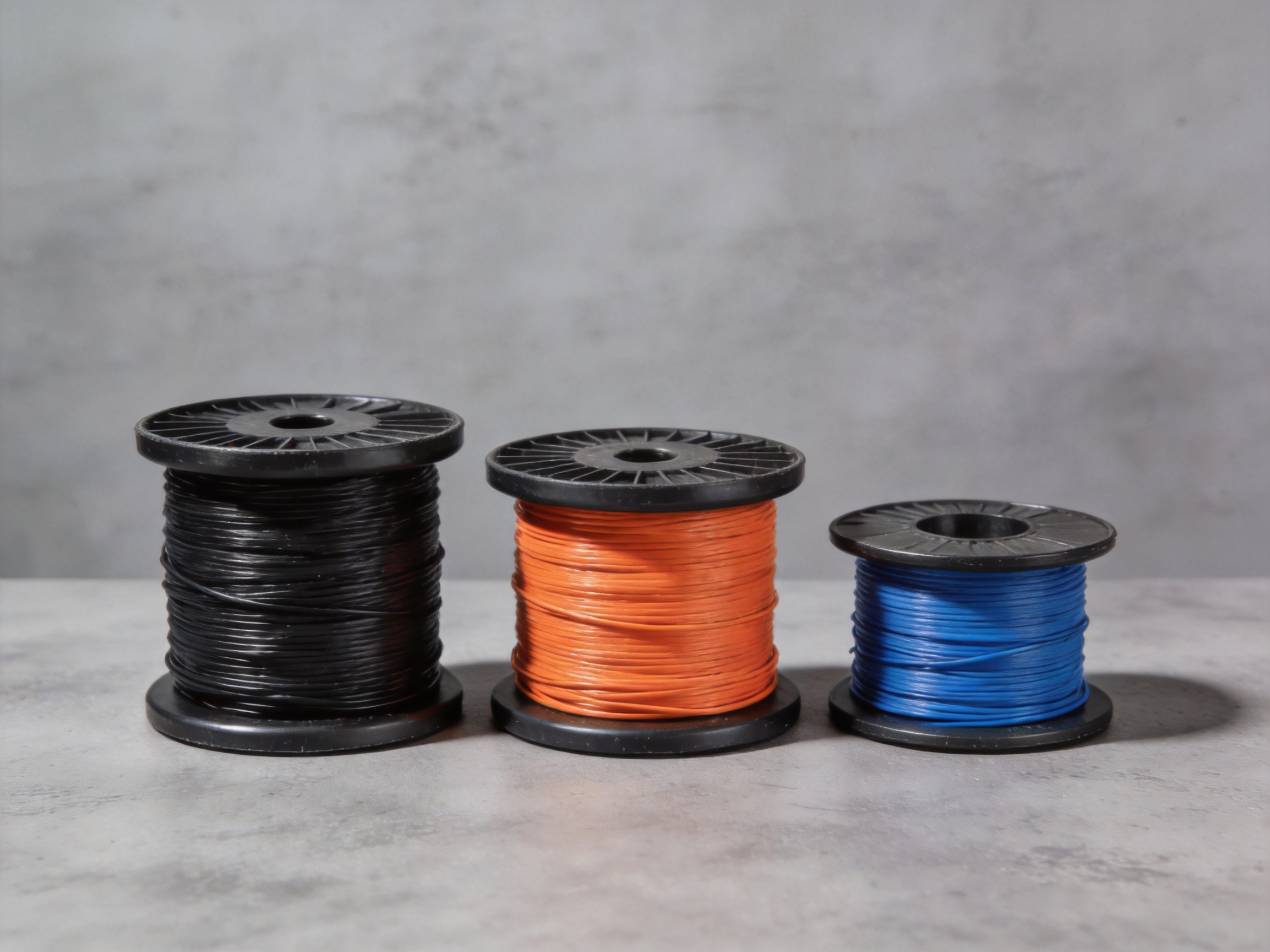
The primary driver of copper wire price is the raw material cost, which fluctuates daily on global markets. Insulation type, such as THHN/THWN-2 for general use or specialized welding cable, also significantly impacts the final price per foot. For bulk purchases, prices are typically quoted per 250-foot or 500-foot spool.
As of late 2024, the base price for pure copper can account for over 70% of the total cost of a standard 4 AWG cable. Always verify the conductor material (copper vs. aluminum) and the exact insulation rating before comparing prices.
1.2 Price Comparison by Wire Type
The table below provides a realistic per-foot price range for common 4 AWG wire types in the US market. These are estimates for bulk purchases; retail prices for shorter lengths will be higher.
Wire Type | Typical Application | Price per Foot (Est.) |
4 AWG THHN/THWN-2 (Copper) | Conduit & Indoor Wiring | $1.80 - $2.50 |
4 AWG XHHW-2 (Copper) | Wet Locations & Service Entrance | $2.00 - $2.80 |
4 AWG USE-2/RHH/RHW-2 (Copper) | Underground Service Entry | $2.20 - $3.00 |
4 AWG Welding Cable (Flexible) | High-Flex Machinery & Leads | $2.50 - $3.50 |
2. Creating an Accurate Project Budget
2.1 The Budgeting Formula
To calculate your total wire cost, use this simple formula: (Total Wire Length Needed × Price per Foot) + (Waste Factor × Total Length × Price per Foot). The waste factor accounts for cuts, mistakes, and future repairs, typically ranging from 10% to 15% for complex runs.
For example, a project requiring 500 feet of 4 AWG THHN at $2.20/foot with a 10% waste factor would cost: (500 × $2.20) + (0.10 × 500 × $2.20) = $1,210 total. This method provides a more realistic budget than just the raw material length.
2.2 Tips for Buying in Bulk
Purchasing full spools is the most cost-effective method for larger projects. To maximize savings and efficiency, follow these key practices:
Consolidate needs from multiple projects to meet higher spool quantity discounts
Verify spool length with suppliers, as standard sizes can vary (e.g., 250 ft vs. 500 ft)
Request a quote based on the current COMEX copper price to lock in a rate
Plan for proper storage to protect the wire from damage and environmental factors
Pro Tip: For large-scale commercial projects, FR-CABLE logistics experts recommend ordering a single, consolidated spool for each wire type to minimize waste from multiple cut lengths and simplify inventory management.
FAQS
1. How many amps can 4 AWG wire handle?
Answer: The ampacity of 4 AWG wire depends on the conductor material and temperature rating of the insulation. generally, 4 AWG copper wire is rated for 85 amps at 75°C (167°F) and 95 amps at 90°C (194°F). However, if you are using aluminum 4 AWG wire, the rating drops to roughly 65 amps at 75°C. Always verify with the National Electrical Code (NEC) Table 310.16 for your specific installation environment.
2. What is the physical diameter of 4 AWG wire?
Answer: The bare conductor diameter of 4 AWG wire is approximately 0.2043 inches (5.19 mm). However, the overall thickness will vary depending on the type of insulation (e.g., THHN vs. thick rubber welding cable). When planning for conduit, you must account for the full diameter including the insulation, not just the copper strands.
3. What size circuit breaker or fuse should I use with 4 AWG wire?
Answer: For standard 75°C rated copper wire usage (like in home wiring), a 70-amp or 80-amp breaker is typically used. While the wire may be rated for 85 amps, standard breakers are not usually available in 85-amp sizes, so you may need to round down to 80A for safety, or check if your local code allows rounding up to 90A (though rounding down is safer). For DC applications like car audio, fuse sizing should match the total current draw of your amplifier, provided it does not exceed the wire's maximum rating.
4. What are the common applications for 4 AWG wire?
Answer: 4 AWG is a versatile "medium-heavy" gauge used in a variety of settings:
Residential: Wiring for large appliances like electric ranges, ovens, and HVAC units, or feeding small sub-panels (e.g., to a detached garage).
Automotive/Marine: Battery cables, alternator wiring, and powering high-wattage car audio amplifiers.
Solar/Off-Grid: Connecting battery banks and connecting charge controllers to batteries in 12V, 24V, or 48V systems.
5. How far can I run 4 AWG wire before voltage drop becomes an issue?
Answer: This depends on the load (amps) and the voltage of the system.
12V DC System: 4 AWG is excellent for minimizing voltage drop. At a 100A load, you can run it about 10–12 feet before seeing a significant drop.
240V AC System: At a 70A load, you can typically run 4 AWG copper wire up to 100 feet while keeping voltage drop under 3%.
Note: Always use a voltage drop calculator for precise planning, as long distances generally require upgrading to a thicker wire (like 2 AWG) to maintain efficiency.


Comments