
Cable Construction and Dimensional Testing: A Complete Guide to Cable Structure, Thickness and Diameter Measurement

A cable can look perfectly normal from the outside and still fail to meet its design or performance requirements.
The conductor may contain an incorrect wire configuration. The insulation may be thinner on one side than the other. The outer sheath may fall below its specified minimum thickness. The finished cable diameter may also exceed the dimensional limits required for connectors, glands, conduits or installation systems.
This is why cable construction and dimensional testing is an essential part of cable manufacturing and quality control.
Dimensional testing verifies whether the physical construction of a cable corresponds to its design specification and applicable product standard. Typical measurements include conductor dimensions, insulation thickness, sheath thickness, overall diameter, ovality and concentricity.
Independent cable-testing laboratories also identify dimensional testing as an important part of wire and cable conformity assessment because dimensional deviations can affect electrical performance, mechanical integrity and installation compatibility.
This guide explains what is measured, how dimensional inspection is performed and why these measurements matter when evaluating cable quality.

What Is Cable Construction?
Cable construction describes the physical arrangement of the materials and components that make up a finished cable.
Depending on the cable type, the construction may include:
Conductor
Conductor screen
Insulation
Insulation screen
Fillers
Binder or separator
Metallic screen
Inner sheath
Armour
Outer sheath
Not every cable contains every layer.
For example, a typical single-core photovoltaic cable may have a relatively simple construction consisting of a flexible conductor, cross-linked insulation and cross-linked outer sheath. IEC 62930 applies to single-core cross-linked insulated and sheathed cables intended for the DC side of photovoltaic systems up to 1.5 kV DC.
Medium-voltage power cables, by comparison, may contain conductor screens, insulation screens and metallic screens in addition to insulation and sheath layers.
Dimensional inspection must therefore be performed according to the construction of the specific cable and the requirements of the applicable cable standard.
What Is Cable Dimensional Testing?
Cable dimensional testing is the measurement of critical physical dimensions of a finished cable or its individual components.
Typical measurements include:
Measurement | What Is Checked | Why It Matters |
Conductor construction | Wire number, wire size and conductor geometry | Electrical resistance and current-carrying performance |
Insulation thickness | Minimum and measured wall thickness | Electrical insulation and mechanical protection |
Sheath thickness | Thickness of the protective outer layer | Environmental and mechanical protection |
Overall diameter | External cable diameter | Connector, gland and installation compatibility |
Ovality | Difference between maximum and minimum OD | Manufacturing consistency |
Eccentricity | Uniformity of insulation around the conductor | Prevents excessively thin insulation areas |
Concentricity | Alignment of conductor and insulation layers | Structural and electrical uniformity |
A dimensional test therefore does much more than determine whether a cable is simply "thick enough."
It determines whether the cable geometry has been controlled correctly throughout manufacturing.

Cable Conductor Construction and IEC 60228
The conductor is one of the first components that should be examined during cable construction inspection.
IEC 60228:2023 specifies nominal conductor cross-sectional areas from 0.5 mm² to 3,500 mm² for a wide range of insulated cable conductors. It also contains requirements relating to wire number, wire dimensions and conductor resistance.
Typical conductor classes include:
Class 1 — solid conductors
Class 2 — stranded conductors
Class 5 — flexible conductors
Class 6 — highly flexible conductors
The conductor class selected depends on the cable application and relevant product standard.
Does a 6 mm² Cable Have to Measure Exactly 6 mm²?
This is a common misunderstanding in cable purchasing.
A nominal 6 mm² conductor does not mean that a buyer should simply measure the outside diameter of the conductor with a caliper, calculate an area and expect exactly 6.000 mm².
"6 mm²" is a nominal conductor size.
IEC 60228 controls conductor construction through requirements that include wire dimensions and maximum conductor resistance. The 2023 edition also includes guidance on dimensional limits for circular conductors.
For this reason, conductor quality should not be judged solely from visual diameter.
A proper inspection should combine:
construction inspection + dimensional verification + DC conductor resistance testing.
This is especially important when comparing cables from different suppliers.
Insulation Thickness Testing
Insulation thickness is one of the most important dimensional characteristics of an electrical cable.
The insulation must provide sufficient separation between the conductor and surrounding conductive materials while maintaining the mechanical and thermal properties required by the product design.
IEC 60811-201 provides methods for measuring insulation thickness for commonly used insulating compounds, including cross-linked materials, PVC, PE and PP. The current consolidated edition incorporates amendments through 2023.
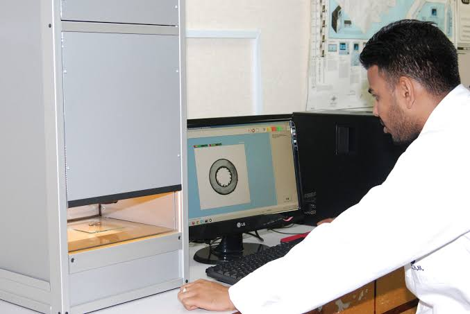
How Is Cable Insulation Thickness Measured?
A typical laboratory inspection involves preparing a clean cable cross-section perpendicular to the cable axis.
The sample can then be examined using suitable optical or dimensional measuring equipment.
Measurements are taken around the insulation wall to determine whether the thickness is sufficiently uniform.
Depending on the applicable product standard, the evaluation may consider:
Nominal insulation thickness
Average measured thickness
Minimum measured thickness
Local thin points
Insulation eccentricity
The exact acceptance requirement must always be taken from the applicable cable product standard rather than from IEC 60811 alone.
IEC 60811 defines the test method; the relevant cable standard generally specifies what thickness the product is required to achieve.
Why Minimum Insulation Thickness Matters
Two cables can have the same average insulation thickness but very different quality.
Consider this simplified example:
Measurement Point | Cable A | Cable B |
Point 1 | 0.82 mm | 1.00 mm |
Point 2 | 0.84 mm | 0.98 mm |
Point 3 | 0.83 mm | 0.99 mm |
Point 4 | 0.81 mm | 0.65 mm |
Point 5 | 0.83 mm | 1.12 mm |
Point 6 | 0.82 mm | 1.15 mm |
Cable B may still have a relatively high average thickness, but one side contains a significantly thinner insulation wall.
That thin region can be more important than the average value.
For quality control, engineers therefore examine both overall thickness and insulation uniformity.
Cable Insulation Eccentricity
Insulation eccentricity occurs when the conductor is not centered correctly within the insulation layer.
Instead of having approximately uniform insulation around the complete conductor circumference, one side becomes thicker while the opposite side becomes thinner.
Research on cable eccentricity notes that significant eccentricity can distort electric-field distribution and contribute to insulation-performance problems, particularly in power-cable applications.
What Causes Cable Eccentricity?
Possible manufacturing causes include:
Extrusion die misalignment
Improper conductor centering
Uneven conductor tension
Conductor vibration
Unstable extrusion pressure
Incorrect tooling adjustment
Variations in cooling
Excessive production-line speed
Conductor geometry variation
Modern production lines may use online diameter or eccentricity monitoring systems to detect these conditions during extrusion rather than waiting for final laboratory inspection.
A Simple Way to Evaluate Thickness Variation
Engineers often compare the maximum and minimum measured insulation thickness around the cable cross-section.
For example:
Maximum insulation thickness = 1.10 mm Minimum insulation thickness = 0.90 mm
The difference is:
1.10 − 0.90 = 0.20 mm
A larger difference generally indicates less uniform insulation geometry.
However, the precise eccentricity or concentricity formula and permitted value should be based on the relevant cable specification or quality-control procedure.

Cable Sheath Thickness Testing
The outer sheath protects the internal cable construction from mechanical damage and environmental exposure.
Depending on the application, the sheath may need to resist:
Abrasion
Moisture
Oils
Chemicals
UV exposure
Mechanical impact
Installation stress
IEC 60811-202 provides test methods for measuring the thickness of non-metallic cable sheaths, including commonly used cross-linked, PVC, PE and PP materials. Its current consolidated version incorporates amendments through 2023.
Why Sheath Thickness Must Be Controlled
A sheath that is too thin may reduce mechanical protection.
But excessive thickness is not automatically an indication of superior cable quality either.
Over-extrusion can:
Increase cable diameter
Increase cable weight
Increase material consumption
Reduce production efficiency
Create connector or cable-gland compatibility problems
Change flexibility
Good cable manufacturing therefore focuses on controlled thickness, not simply maximum thickness.
Overall Cable Diameter Measurement
Overall diameter, commonly abbreviated as OD, is the external diameter of the completed cable.
IEC 60811-203 specifies methods for measuring overall dimensions and applies to both circular and flat cables.
OD is important because cable diameter affects much more than appearance.
It can influence:
Cable gland selection
Connector compatibility
Conduit filling
Cable tray capacity
Minimum bending radius
Drum capacity
Packaging
Installation space
For solar cables, for example, outside diameter can also influence compatibility with photovoltaic connectors and sealing systems.
How Is Cable Overall Diameter Measured?
For circular cables, measurements may be taken across the cable in more than one direction.
A simplified example:
Diameter measurement 1 = 6.20 mm Diameter measurement 2 = 6.28 mm
Average diameter:
(6.20 + 6.28) ÷ 2 = 6.24 mm
If a cable is visibly non-circular, both maximum and minimum diameters can provide useful information about the extrusion process.
What Is Cable Ovality?
Ovality describes how far a circular cable departs from a perfect circular shape.
A cable with good circularity should have similar diameters when measured along different axes.
For example:
Maximum OD = 10.4 mm Minimum OD = 10.0 mm
Diameter difference:
10.4 − 10.0 = 0.4 mm
A simplified engineering ovality indicator can also be expressed as:
Ovality (%) = (Maximum OD − Minimum OD) / Average OD × 100
The acceptable limit depends on the cable design and applicable specification.
Excessive ovality can indicate:
Uneven extrusion
Improper cooling
Cable deformation
Incorrect take-up tension
Improper storage
Excessive pressure during winding
It may also create problems when cables must pass through glands, seals or connectors with tight dimensional tolerances.
Cable Cross-Section Inspection
A well-prepared cable cross-section reveals a surprising amount of information about manufacturing quality.
Engineers can visually inspect:
Conductor centering
Insulation uniformity
Sheath uniformity
Layer adhesion
Fillers
Screens
Armour position
Voids
Surface defects
Layer concentricity
Modern image-analysis systems can also calculate dimensions such as diameter, minimum wall thickness, mean thickness and eccentricity from cross-sectional images. Research has demonstrated automated image-based methods for measuring these parameters in power-cable cross-sections.
For cable manufacturers, cross-section inspection is therefore one of the fastest ways to identify extrusion and structural problems.
Typical Equipment Used for Cable Dimensional Testing
Depending on cable type, required accuracy and laboratory capability, dimensional measurements may use:
Micrometers
Useful for certain conductor, wire and material measurements.
Vernier or Digital Calipers
Often used for general dimensional checks, although they may not be sufficient for every precision thickness measurement.
Measuring Microscope
Allows technicians to inspect prepared cable cross-sections and accurately determine layer thickness.
Profile Projector
Magnifies the cable cross-section so multiple dimensions can be measured.
Digital Image Measurement Systems
Computer-assisted systems can identify layer boundaries and calculate parameters such as:
Diameter
Insulation thickness
Sheath thickness
Eccentricity
Concentricity
Ovality
Online Diameter and Eccentricity Gauges
Extrusion lines may incorporate laser, optical, ultrasonic, X-ray or other non-contact systems for continuous process monitoring.
Online monitoring allows operators to correct extrusion conditions before large quantities of non-conforming cable are produced.
Dimensional Testing vs Electrical Testing
Dimensional inspection alone cannot determine whether a cable is electrically compliant.
Likewise, electrical testing alone may not reveal every structural defect.
A comprehensive cable QC program normally combines several types of tests.
Test Category | Examples |
Dimensional | Insulation thickness, sheath thickness, OD, eccentricity |
Electrical | Conductor resistance, voltage test, insulation resistance |
Mechanical | Tensile strength, elongation, abrasion |
Thermal | Heat ageing, hot-set, thermal endurance |
Environmental | UV, ozone, water, chemical resistance |
Fire performance | Flame propagation, smoke, halogen performance |
For conductor verification in particular, dimensional inspection should be considered together with DC resistance testing.
IEC 60228 includes conductor resistance requirements in addition to conductor construction requirements.
Is a Thicker Cable Always Better?
No.
This is an important point for cable buyers.
A cable with a larger external diameter does not necessarily contain more copper.
The larger diameter may result from:
Thicker insulation
Thicker sheath
Additional fillers
Different insulation materials
Different conductor construction
Different cable design
Therefore:
Cable OD ≠ conductor cross-sectional area.
Similarly:
A heavier cable ≠ automatically a better cable.
A technically meaningful comparison should consider:
Conductor material
Nominal conductor size
Conductor class
DC resistance
Insulation material
Insulation thickness
Sheath construction
Overall diameter
Applicable standard
Test results
This is especially important when comparing quotations from multiple cable suppliers.
Common Dimensional Defects Found in Cable Manufacturing
Insulation Too Thin
Possible causes include excessive line speed, incorrect extrusion settings or tooling problems.
Uneven Insulation Thickness
Often associated with conductor misalignment or extrusion-die centering.
Excessive Cable Diameter
May result from excessive material extrusion, incorrect tooling or dimensional control problems.
Excessive Ovality
Can be related to cooling, take-up tension or cable deformation.
Thin Outer Sheath
May reduce mechanical protection and cause non-compliance with product specifications.
Oversized or Undersized Conductor Construction
Can affect electrical resistance, material cost and compliance.
Inconsistent Strand Diameter
May indicate conductor-production process variation.
Finding these problems during production is significantly preferable to discovering them after an entire cable batch has been manufactured.
Which IEC Standards Are Relevant to Cable Dimensional Testing?
Several IEC standards are commonly associated with dimensional inspection.
Standard | Main Purpose |
IEC 60228:2023 | Conductors of insulated cables |
IEC 60811-201 | Measurement of insulation thickness |
IEC 60811-202 | Measurement of non-metallic sheath thickness |
IEC 60811-203 | Measurement of overall dimensions |
IEC 62930 | Photovoltaic cables up to 1.5 kV DC |
IEC 60811-201 and IEC 60811-202 have consolidated editions incorporating amendments published through 2023.
It is important to distinguish between a test-method standard and a product standard.
IEC 60811 primarily explains how certain tests are performed.
The applicable cable product standard defines the construction and acceptance criteria that the cable must satisfy.
What Should Cable Buyers Check in a Dimensional Test Report?
When evaluating a supplier's inspection report, buyers should look beyond a simple "PASS" statement.
A useful report should identify:
Cable specification
Cable size
Batch or production lot
Applicable standard
Test method
Nominal requirement
Actual measured values
Minimum and maximum measurements
Test equipment where applicable
Test date
Pass/fail conclusion
For insulation and sheath measurements, actual values from multiple measurement points provide much more useful information than a single average value.
For conductor evaluation, DC resistance results should also be reviewed where applicable.
Why Dimensional Control Matters During Cable Manufacturing
Cable manufacturing is a continuous process.
Small dimensional deviations can therefore affect hundreds or thousands of meters of product before they become obvious.
Effective manufacturers control dimensions at several stages:
Raw material inspection → conductor production → extrusion → online dimensional monitoring → finished cable inspection → laboratory verification → final QC
This approach allows production teams to identify process drift early.
It also reduces:
Material waste
Rework
Scrap
Customer complaints
Installation problems
Certification risk
Dimensional testing is therefore not simply a final inspection activity.
It is part of process control.
Cable Dimensional Testing Checklist for Buyers
Before approving a cable supplier or shipment, consider checking:
Is the conductor construction consistent with the specified standard?
Has conductor resistance been tested?
Is insulation thickness measured at several positions?
Is the minimum insulation thickness recorded?
Is sheath thickness measured?
Is the finished cable OD within specification?
Has ovality or dimensional variation been evaluated?
Is conductor centering acceptable?
Is the cable cross-section visually uniform?
Are test instruments calibrated?
Can the manufacturer provide batch inspection records?
Are the test standards clearly stated?
These questions provide a much better indication of manufacturing quality than comparing cable appearance alone.
Frequently Asked Questions
What is dimensional testing of cables?
Cable dimensional testing measures physical characteristics such as conductor dimensions, insulation thickness, sheath thickness, overall cable diameter, eccentricity and ovality to verify that the cable construction complies with its specification.
Which standard is used for cable insulation thickness measurement?
IEC 60811-201 provides methods for measuring cable insulation thickness for common insulating compounds such as cross-linked materials, PVC, PE and PP.
Which standard is used for cable sheath thickness?
IEC 60811-202 covers measurement methods for non-metallic cable sheath thickness.
Which standard covers cable overall diameter?
IEC 60811-203 provides methods for measuring the overall dimensions of circular and flat cables.
Does cable diameter determine conductor size?
No. Cable outside diameter includes the conductor, insulation, sheath and any additional construction layers. Conductor compliance should be evaluated using the applicable conductor requirements and electrical resistance testing rather than overall cable diameter alone.
Why is cable eccentricity important?
High eccentricity produces an uneven insulation wall, creating a thinner region on one side of the conductor. Dimensional inspection helps identify this condition before the cable is approved.
Conclusion
Cable quality cannot be determined simply by looking at the outside of the cable.
A properly manufactured cable requires controlled conductor construction, insulation thickness, sheath thickness, overall dimensions and layer uniformity.
Standards such as IEC 60228, IEC 60811-201, IEC 60811-202 and IEC 60811-203 provide an important technical framework for conductor and dimensional evaluation.
For cable manufacturers, dimensional testing provides immediate feedback about conductor production and extrusion quality.
For buyers, engineers and inspectors, it provides something equally important:
measurable evidence that the cable has been manufactured according to its intended design rather than simply made to look correct.




That's Not My Neighbor makes a simple job feel strangely stressful. You check each visitor, look over their documents, and try to catch anything that seems off. One small mistake can be enough to let the wrong person into the building.