
How Far Can 10 AWG Wire Really Run? A Voltage-Drop Guide for 12V, 24V, and 48V Battery and Solar Systems

Introduction
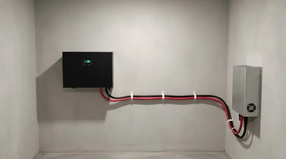
Most 10 AWG reference charts stop at the same headline number: 30 amps. That figure is accurate, and it answers a real question — but it is the wrong question for anyone wiring a battery bank, an off-grid cabin, or a DC solar system. In those circuits, the conductor almost never gets hot enough to trip a breaker. It fails quietly instead, by letting voltage sag away before it reaches the load.
This guide sets ampacity aside and focuses on the variable that actually decides whether 10 AWG is the right wire for a low-voltage DC run: distance. Using standard copper resistance values, it walks through how far 10 AWG can carry real currents at 12V, 24V, and 48V before voltage drop eats into system performance — with worked tables you can apply directly to a battery bank, inverter feed, or array wiring layout.
Why Voltage Drop Hits 12V Systems So Much Harder Than 120V Circuits
Voltage drop is usually expressed as a percentage — commonly 2% for critical loads and up to 3% for general power wiring. That percentage is the same rule of thumb whether the circuit runs at 12V or 240V, but the absolute number of volts it allows is not.
A 3% budget on a 120V circuit allows about 3.6 volts of loss before performance is affected. The same 3% budget on a 12V battery circuit allows only about 0.36 volts. The wire has not changed — the room for error has simply shrunk by a factor of ten. This is the core reason a cable size that works comfortably on a 120V/240V branch circuit can fall apart on a 12V solar or battery run of the same length and current.

10 AWG's Electrical Baseline
The two numbers that drive every calculation in this guide are the conductor's cross-sectional area and its resistance:
• Cross-sectional area: approximately 5.26 mm² (nearest IEC metric size: 6 mm²)
• DC resistance: approximately 3.28 Ω/km for stranded copper at 20°C
• Resistance rises somewhat at higher operating temperatures, so real-world drop on a hot rooftop run will run slightly higher than the reference figures below
These values are what the tables in this guide are built on. If you need the full breakdown of diameter, insulation types, and NEC ampacity tables for 10 AWG, that is covered in more depth elsewhere — this guide is deliberately narrow, focused only on how far the wire can go.

The DC Voltage-Drop Formula, and Why 'Round Trip' Matters
Unlike a single-conductor AC ampacity lookup, a DC voltage-drop calculation has to account for both the outbound and return conductor, because current flows in a complete loop. For a copper conductor:
Voltage drop (V) = Current (A) × 2 × One-way length (km) × Resistance (Ω/km)
For example, 10 AWG carrying 20A over a one-way run of 10 meters: 20A × 2 × 0.010 km × 3.28 Ω/km ≈ 1.31V of drop. On a 12V system, that is already close to 11% of the total voltage — far beyond any acceptable design margin.
Voltage Drop Table: 10 AWG Carrying 20A at Different Distances
The table below holds current constant at 20A — a typical charge or discharge current for a mid-size battery bank or solar string — and varies only the one-way cable length, showing the resulting percentage drop at each common system voltage.
One-Way Distance | Voltage Drop (V) | Percent Drop at 12V | Percent Drop at 24V | Percent Drop at 48V |
5 m | 0.66 V | 5.5% | 2.7% | 1.4% |
10 m | 1.31 V | 10.9% | 5.5% | 2.7% |
15 m | 1.97 V | 16.4% | 8.2% | 4.1% |
20 m | 2.62 V | 21.9% | 10.9% | 5.5% |
30 m | 3.94 V | 32.8% | 16.4% | 8.2% |
50 m | 6.56 V | 54.7% | 27.3% | 13.7% |
The pattern is unmistakable: at 12V, 10 AWG carrying 20A is already past a reasonable drop budget before the cable even reaches 5 meters. At 48V, the same cable and the same current stay within a workable range out to roughly 20–30 meters. Nothing about the wire changed — only the system voltage did.
Maximum Cable Run for 10 AWG Within a 3% Drop Budget
Turning the same numbers around answers the more practical question: for a given current, how far can 10 AWG go before it crosses a 3% drop budget?
Current | Max One-Way Run at 12V | Max One-Way Run at 24V | Max One-Way Run at 48V |
10 A | ≈ 5.5 m | ≈ 11.0 m | ≈ 22.0 m |
20 A | ≈ 2.7 m | ≈ 5.5 m | ≈ 11.0 m |
30 A | ≈ 1.8 m | ≈ 3.7 m | ≈ 7.3 m |
For a target closer to 2% — recommended for charge controllers, sensitive electronics, and any load where voltage stability matters — multiply the distances above by roughly two-thirds. This table is also why 12V battery banks are almost always built with very short, heavy cable runs between battery and inverter, while 24V and 48V systems have far more flexibility in physical layout.
What This Looks Like in Real Installations
12V Off-Grid Cabin or RV House Bank
A 12V system pulling 20A from battery to inverter has a workable 10 AWG run of under 3 meters one-way before drop becomes a real problem. In most RVs and small cabins, that is tight but achievable if the battery sits close to the inverter — it is not achievable if the battery bank is in a separate compartment 6–8 meters away. That gap is exactly where installers reach for 4 AWG or 2 AWG instead, even though 10 AWG is thermally rated for far more current than 20A.

24V Trailer, Golf Cart, or Small Solar Trailer System
Doubling the system voltage to 24V roughly doubles the workable distance for the same current and the same percentage drop. A 20A, 5-meter run that was marginal at 12V sits comfortably within budget at 24V, which is one of the practical reasons mobile and trailer-based solar systems increasingly standardize on 24V architecture rather than 12V.
48V Home Battery to Hybrid Inverter
At 48V, 10 AWG carrying 20A has roughly 11 meters of one-way headroom before hitting a 3% drop — enough for many residential battery-to-inverter placements without upsizing. This is a major reason 48V has become the default for larger home battery systems: it lets a moderate-gauge conductor do the work that would require a much heavier cable at 12V.
Ground-Mounted Solar Arrays with Long Homerun Cables
Ground-mount arrays often need to send string current 15–30 meters back to a combiner box or inverter. Even at a comfortable 48V string voltage, a 30-meter run carrying 20A sits right at the edge of a 3% budget — which is why long homerun cables are one of the most common places projects step up from 10 AWG to 8 AWG or 6 AWG, independent of what the ampacity table would otherwise allow.

When to Size Up from 10 AWG on a DC Run
• The system operates at 12V and the run exceeds roughly 3–5 meters at moderate current
• The load is current-sensitive (chargers, inverters, electronics) and a 2% budget applies instead of 3%
• The installation is in a hot environment (rooftop, engine bay, enclosed battery box), where resistance rises above the 20°C reference values used in these tables
• Multiple loads share the same feeder, stacking currents beyond a single 10–20A branch
• The run length is fixed by the installation (battery compartment location, array-to-combiner distance) and cannot be shortened
In any of these cases, the fix is rarely a different type of 10 AWG cable — it is a larger conductor. Stepping up to 8 AWG roughly cuts resistance, and therefore drop, by about a third for the same run; 6 AWG cuts it further still.
Common Mistakes When Wiring 10 AWG for Battery and Solar DC Circuits
• Sizing the cable from an ampacity chart alone, without ever running a voltage-drop calculation for the actual system voltage
• Measuring only the straight-line distance between battery and load instead of the actual routed, round-trip cable length
• Applying a 120V-circuit mindset to a 12V circuit, where the same percentage budget translates to a fraction of the usable distance
• Forgetting that fuses, breakers, connectors, and battery terminals each add a small amount of additional resistance on top of the cable itself
• Using the 20°C reference resistance for a cable that will operate hot inside an enclosed battery box or on a sun-exposed rooftop
• Assuming a longer homerun cable can be fixed later by adding a larger inverter or charge controller — the loss happens in the wire, not the equipment
Quick Reference: 10 AWG for International and Metric-Based Buyers
For teams sourcing cable against IEC or EN specifications rather than NEC tables, 10 AWG's cross-section of approximately 5.26 mm² is commonly matched with 6 mm² cable — the nearest standard metric size at or above the AWG equivalent. The resistance and voltage-drop figures used throughout this guide remain valid whether the cable is labeled 10 AWG or 6 mm², since the calculation depends on the physical copper cross-section rather than the label on the spool.
Frequently Asked Questions
Q1: How far can 10 AWG wire run at 12V?
A: For a 3% voltage-drop budget, 10 AWG at 12V supports roughly 5.5 meters one-way at 10A, and only about 2.7 meters one-way at 20A. Longer runs at meaningful current require a larger conductor or a higher system voltage.
Q2: Does 10 AWG need to be larger for a 24V system than a 12V system?
A: The wire itself doesn't change, but the workable distance roughly doubles at 24V compared with 12V for the same current and the same percentage drop, because the allowable voltage loss scales with system voltage.
Q3: What voltage-drop percentage should I design for in a solar or battery system?
A: 3% is a common general-purpose target; 2% is a tighter, more conservative target often used for charge controllers, inverters, and other voltage-sensitive equipment.
Q4: Can I use 10 AWG for a long inverter cable run?
A: It depends on system voltage and current. At 48V and moderate current, 10 AWG can often support a 10-meter-plus run within a 3% budget; at 12V, the same current limits the practical run to a few meters before a larger cable is needed.
Q5: Is ampacity or voltage drop the limiting factor for 10 AWG in DC systems?
A: In most battery and solar DC wiring, voltage drop reaches its limit long before the conductor approaches its thermal ampacity rating — which is why gauge selection for these circuits should start with a voltage-drop calculation, not an ampacity chart.
Q6: Does temperature affect these voltage-drop numbers?
A: Yes. The figures in this guide use 20°C reference resistance. A cable operating hot — inside an enclosed battery box or on a sun-exposed rooftop — will have somewhat higher resistance and correspondingly more drop than these baseline figures show.
Conclusion
10 AWG's 30-amp ampacity rating is real, but in 12V, 24V, and 48V battery and solar systems it is rarely the number that decides whether the cable is the right choice. Distance is. A run that is comfortably short at 48V can be entirely impractical at 12V using the exact same wire and the exact same current — and no amount of ampacity headroom changes that math.
Before locking in 10 AWG for a battery bank, inverter feed, or array homerun, run the voltage-drop numbers for your actual system voltage and actual routed cable length. If the run falls outside a comfortable 2–3% budget, stepping up to 8 AWG or 6 AWG — or reconsidering the physical layout — will do more for system performance than any other single wiring decision.
Source Voltage-Optimized DC and Solar Cable from FRCABLE
FRCABLE supplies stranded copper cable for battery, solar, and low-voltage DC applications in both 10 AWG and its 6 mm² metric equivalent, including:
• Flexible fine-strand copper conductors sized for accurate, predictable resistance values
• XLPE and XLPO insulation options rated for battery enclosures, rooftop exposure, and outdoor DC runs
• Documentation to support voltage-drop calculations across 12V, 24V, and 48V system designs
• Larger gauges (8 AWG, 6 AWG, 4 AWG / 10 mm², 16 mm², 25 mm²) for projects where distance rules out 10 AWG
Our technical team can help match conductor size to your specific system voltage, current, and cable-run length before you finalize a procurement order.


all right