10 AWG vs 12 AWG Wire: Which One Should You Choose for 30A Loads?
- Vicky

- 2 hours ago
- 12 min read

A 30-amp circuit is the backbone of countless residential and commercial electrical installations—from clothes dryers and RV hookups to solar combiner boxes and subpanel feeders. The gauge of wire you run to serve that 30A load is not a casual choice. I’ve stood in front of open breaker panels where 12 AWG wire was landed on a 30-amp breaker, and I’ve had to break the news: this is a code violation, and it’s also a fire waiting to happen. Other times, 10 AWG was overkill from a purely thermal standpoint, but voltage drop at 150 feet forced its use anyway. The 10 AWG vs 12 AWG wire debate is more nuanced than “bigger is better.”
Understanding when 12 AWG can legally and safely serve a 30A load, and why 10 AWG is the default correct answer, requires diving into ampacity tables, the NEC’s 80% rule for continuous loads, insulation temperature ratings, and voltage drop calculations. This article is a practitioner’s guide—drawing on 20 years of specifying and inspecting wire in solar, residential, and light commercial systems—to help you make a code-compliant, thermally safe, and economically rational wire gauge decision for anything that pulls 30 amps.
Understanding Wire Gauge and Ampacity: The Foundation of Circuit Design
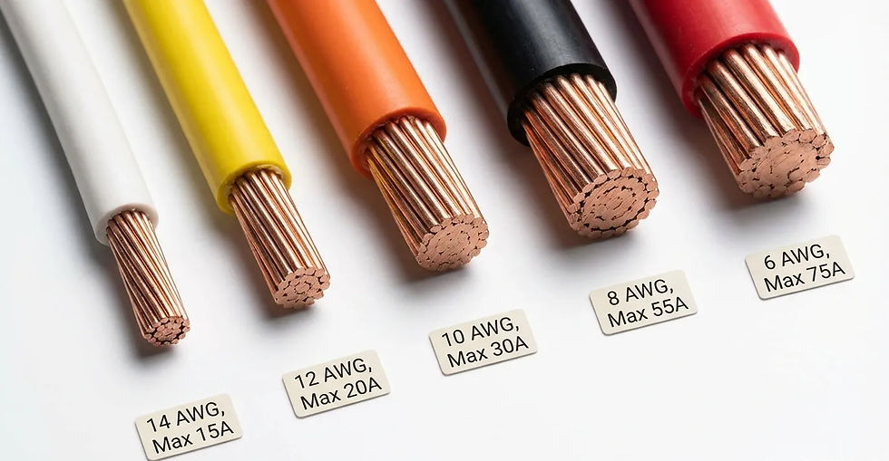
Wire gauge is a measure of conductor cross-sectional area, not just thickness. The American Wire Gauge system is inverse: a smaller number means a larger conductor. 10 AWG wire has a diameter of 2.588 mm and a cross-section of 5.26 mm². 12 AWG wire measures 2.053 mm in diameter and 3.31 mm² in cross-section. The difference in copper volume translates directly into lower resistance per foot for 10 AWG, which means less heating at the same current.
What Ampacity Really Means
Ampacity is the maximum continuous current a conductor can carry without exceeding its temperature rating under stated conditions. Those “stated conditions” include the insulation type, ambient temperature, and number of current-carrying conductors in a raceway or cable. Change one variable—run the wire through a hot attic instead of a cool basement—and the ampacity drops.
Wire doesn’t fail like a fuse; it fails by degrading insulation. A 12 AWG copper conductor can physically pass 35 amps for a short time without melting, but the PVC or XLPE jacket surrounding it will soften, embrittle, and eventually short out if operated above its temperature rating. This is why ampacity tables are conservative. They’re designed to ensure insulation integrity over decades, not seconds.
The 60°C, 75°C, and 90°C Insulation Columns
Most NEC ampacity tables give three temperature columns—60°C, 75°C, and 90°C—reflecting the maximum operating temperature of the conductor’s insulation. Common wire types and their typical use columns:
TW/UF (60°C): Older or underground-rated wire, restricted to the 60°C column.
THHN/THWN-2 (75°C or 90°C): Most modern building wire; can use the 75°C column for termination ampacity, with 90°C rating used for derating calculations.
XHHW-2 (90°C): Cross-linked polyethylene, used frequently in solar and industrial; also uses the 75°C termination column.
The limiting factor is nearly always the 75°C column because circuit breakers and terminals are rated for 75°C unless otherwise marked. This detail is critical to the 10 AWG vs 12 AWG decision.
NEC Code Rules for 10 AWG and 12 AWG Wire Sizing
The National Electrical Code (NEC) governs wire sizing in the United States. Its rules are not suggestions; they’re adopted into law by local jurisdictions. For 30A loads, two sections matter above all others: Article 310 (ampacity tables) and Article 240.4(D) (small conductor overcurrent protection limits).
Continuous vs. Non-Continuous Loads: The 80% Rule
NEC defines a continuous load as one where the maximum current is expected to continue for three hours or more. Most residential loads—space heaters, water heaters, electric vehicle chargers, solar inverters at peak production, large lighting banks—qualify as continuous. For a continuous load, the conductor ampacity must be at least 125% of the load current. In practical terms, a 30A continuous load requires a wire ampacity of at least 37.5 amps after all derating.
If the load is non-continuous—say, a welder with a low duty cycle—the wire only needs to handle 30 amps. But most circuits are wired assuming the load could be continuous, because it’s safer and often mandated by the appliance manufacturer’s installation instructions. So the default mindset is to treat any 30A circuit as continuous unless you can prove otherwise.
NEC Table 310.16 and Small Conductor Ampacity Limits
At 75°C, NEC Table 310.16 assigns:
12 AWG copper: 25 amps
10 AWG copper: 35 amps
Already, the numbers flash a warning: 12 AWG at 75°C can’t even touch 30A. It’s limited to 25 amps. Even at 90°C, 12 AWG copper is rated 30 amps, but you can rarely use the 90°C ampacity for final termination due to breaker terminal limitations (75°C). Furthermore, NEC 240.4(D) places specific overcurrent protection limits on small conductors regardless of ampacity:
12 AWG copper: maximum overcurrent protection is 20 amps, with a few exceptions (motor circuits, welder circuits, specific AC units).
10 AWG copper: maximum overcurrent protection is 30 amps, with similar exceptions.
This is the regulatory hammer. A general-purpose 30A branch circuit wired with 12 AWG and protected by a 30A breaker violates NEC 240.4(D). The wire may thermally survive 30 amps in free air, but code forbids it except under the narrow exceptions detailed in 240.4(G). For almost all residential and commercial applications, 12 AWG wire cannot be used on a 30-amp circuit. This is the single most important takeaway.

Ampacity Comparison: 10 AWG vs 12 AWG Under Different Conditions
Let’s move beyond the code text and look at the raw ampacity numbers, then apply real-world derating. The table below compares the two gauges under the three standard temperature columns, for not more than three current-carrying conductors in a raceway or cable, and for common insulation types.
Condition / Insulation Type | 12 AWG Copper Ampacity | 10 AWG Copper Ampacity | Notes |
60°C column (TW, UF-B) | 20 A | 30 A | NEC 240.4(D) limits: 12 AWG → 20 A; 10 AWG → 30 A |
75°C column (THWN-2, RHW) | 25 A | 35 A | Most terminations; 12 AWG limited to 25 A, still below 30 A |
90°C column (THHN, XHHW-2) | 30 A | 40 A | Cannot be used for final ampacity at breakers rated 75°C; used for derating only |
After 80% continuous load rule (75°C column) | 20 A usable | 28 A usable (close, but allowed per 240.4(D) exception for 30A circuits) | For continuous 30A load, you need 37.5 A ampacity; 10 AWG (35 A) falls slightly short, but NEC 240.4(D) allows 30A breaker if ampacity is 35A or greater and load ≤30A; for truly continuous 30A, some inspectors interpret strictly |
Ambient temperature derated (50°C attic, apply 0.82 factor to 90°C column) | 24.6 A | 32.8 A | 10 AWG still above 30 A; 12 AWG drops below 25 A |
The data is unambiguous: at any temperature column and under any realistic derating condition, 10 AWG copper maintains enough headroom to safely serve a 30A circuit, while 12 AWG copper falls short and is explicitly prohibited by NEC 240.4(D) for most 30A applications. For those rare exceptions where 12 AWG might be allowed—such as a dedicated motor circuit with specific overload protection—careful engineering and local inspector approval are required. In general wiring, choose 10 AWG wire for 30A loads.
When 12 AWG Wire Can (and Can't) Handle 30 Amps
There are industry myths and misunderstandings that keep this debate alive. Let’s address them directly.
The "12 AWG in Free Air" Myth
Yes, a single 12 AWG conductor in free air (not in a cable or raceway) has a higher ampacity. Per NEC Table 310.17, 12 AWG XHHW-2 in free air at 90°C could be rated 40 amps. But residential and commercial wiring is rarely "free air." It’s installed in NM-B cable sheathed inside walls, in conduit with other conductors, or in cable trays with bundling. The moment you do that, you’re back to Table 310.16, and the ampacity collapses to 25 amps at 75°C. The free air argument is practically irrelevant for almost all permanent building wiring.
The Exceptions in NEC 240.4(G)
NEC 240.4(G) lists specific applications where the small conductor limits of 240.4(D) don’t apply: motor circuits, air-conditioning and refrigeration equipment, welders, and some transformer secondary conductors. For these, the conductor may be protected by an overcurrent device sized per the equipment’s specific article. It’s possible—though not common—for a motor nameplate to allow a 12 AWG conductor on a 30-amp breaker when combined with an overload relay providing thermal protection. But for general-purpose receptacles, lighting, or a subpanel feeder, these exceptions do not exist. The electrician who installs 12 AWG NM-B on a 30A breaker for a dryer outlet violates 240.4(D) and creates a liability that insurance may not cover.
12 AWG UF-B for Residential Circuits
Underground feeder cable (UF-B) is restricted to the 60°C column. At 60°C, 12 AWG ampacity is 20 amps, not 25 amps. So even a non-continuous 25-amp circuit would be too much. Any thought of using 12 AWG UF for a 30A load is immediately code-prohibited and dangerous. This is a common mistake made by homeowners running wire to a shed or RV pad; the wire gets hot, the breaker doesn't trip, and the underground cable degrades at an accelerated rate until it faults. I’ve personally excavated failed UF-B lines that were crispy and carbonized from years of overload—all running on what the owner thought was a “safe” 30-amp connection.
Voltage Drop Considerations: Why Distance Matters
Even if 12 AWG could thermally handle 30A (which it cannot per code), voltage drop would often force an upsizing to 10 AWG, or even 8 AWG, for longer runs. Excessive voltage drop reduces equipment efficiency and can cause inverters or motors to trip offline.
Calculating Voltage Drop for 12 AWG vs 10 AWG
Voltage drop is calculated as:Vd = (2 × L × I × R) / 1000 (for a single-phase circuit, where R is resistance per 1000 ft).For 12 AWG copper, resistance is approximately 1.588 Ω/1000 ft at 75°C.For 10 AWG copper, resistance is approximately 0.9989 Ω/1000 ft at 75°C.
For a 30A load at 120V, running 100 feet (one-way), the voltage drop is:
12 AWG: Vd = (2 × 100 × 30 × 1.588) / 1000 = 9.53 V, or 7.94%.
10 AWG: Vd = (2 × 100 × 30 × 0.9989) / 1000 = 5.99 V, or 4.99%.
The NEC recommends a maximum voltage drop of 3% for feeders and 5% total to the farthest outlet (feeder + branch circuit). At 100 feet, 10 AWG is just barely acceptable for a 120V 30A load; 12 AWG fails badly. For a 240V circuit, the percentages halve, but 12 AWG still exceeds the 3% feeder recommendation on runs over 60-70 feet.
The table below provides a quick reference for common distances at 240 V, 30 A (typical for dryers, water heaters):
One-way distance (ft) | 12 AWG Voltage Drop (%) | 10 AWG Voltage Drop (%) | Recommended Gauge for ≤3% VD |
50 ft | 0.99% | 0.62% | 12 AWG (if code allowed) or 10 AWG |
75 ft | 1.49% | 0.94% | 10 AWG |
100 ft | 1.98% | 1.25% | 10 AWG |
150 ft | 2.98% | 1.87% | 10 AWG (borderline) |
200 ft | 3.97% | 2.49% | 8 AWG for longer life |
For 120 V loads, all percentages double. Therefore, voltage drop alone often mandates 10 AWG or larger for any 30A circuit running beyond a very short distance, even if the ampacity were somehow sufficient.
Practical Guide: How to Select the Right Wire for 30A Loads
Use this ordered process when designing or installing a 30A circuit:
Confirm the load type and continuous classification.Check the appliance nameplate or installation manual. If the load can run for three hours or more, treat it as continuous and apply the 125% rule. For a 30A continuous load, you need at least 37.5A ampacity—pushing you toward 8 AWG in some cases, though 10 AWG with 90°C insulation and proper termination can suffice per common practice, as long as the breaker is 30A and the load is no more than 30A.
Determine the minimum ampacity required from the NEC table.Use the 75°C column for most terminations. If the calculated ampacity is ≤30 A, 10 AWG is the smallest legal general-use conductor per 240.4(D). 12 AWG is never code-compliant for general 30A circuits.
Apply any derating factors.If the wire runs through an attic that reaches 130°F (55°C), apply the appropriate temperature correction factor from NEC Table 310.15(B)(1)(1). If you have four or more current-carrying conductors in a conduit, apply the adjustment factor from Table 310.15(C)(1). The derated ampacity must still meet or exceed the load requirement.
Calculate voltage drop for the actual circuit length.Use the formula or an online calculator. If voltage drop exceeds 3% at the feeder/branch, size up. For long runs, 10 AWG may be insufficient; don't hesitate to jump to 8 AWG if required.
Verify breaker and termination compatibility.Ensure the breaker terminals accept the conductor size (most 30A breakers accept 14–8 AWG; 10 AWG fits easily). Use copper-only fittings if mandated. Torque the terminal to the manufacturer’s specification using a calibrated torque screwdriver—a step many DIYers skip that causes local overheating.
Select the correct insulation type for the environment.Indoors in dry conditions, NM-B (Romex) is standard; but NM-B must be protected. For outdoor or wet locations, use THWN-2 in conduit. For underground direct burial, UF-B is an option but must be sized per the 60°C column (so 10 AWG UF gives 30A). For solar PV source circuits, use UL 4703 PV wire with appropriate temperature and sunlight resistance.
Following these steps eliminates guesswork and ensures you’re not staring at a red tag—or worse, a smoking junction box.
Common Mistakes When Using 10 AWG and 12 AWG Wire
Here are the most frequent errors I encounter in the field:
Landing 12 AWG on a 30-amp breaker for general circuits. This is a direct NEC violation. It may power the load fine initially, but it’s unsafe and uninsurable. If you see it, replace it.
Ignoring termination temperature ratings. Electricians sometimes use the 90°C ampacity of THHN to justify 12 AWG on 30A, forgetting that the breaker terminal is only rated for 75°C (the default). The ampacity must be taken from the lowest temperature rating in the circuit.
Not accounting for voltage drop on long runs. I’ve seen 12 AWG UF run 200 feet to an RV pedestal, then the RV’s air conditioner compressor fails to start due to low voltage. The wire didn’t overheat, but it created a functional failure that cost more to fix than using 10 AWG initially.
Using aluminum wire without proper sizing and anti-oxidation compound. Aluminum has different ampacity and oxidation properties. For 30A, 10 AWG aluminum is generally rated only 25 A at 75°C, so you’d need 8 AWG aluminum. Don’t assume copper ratings apply.
Mixing old and new wiring without checking the entire circuit. A 30A breaker with 10 AWG connected to a junction box that then feeds 12 AWG for the last 10 feet is still a code violation and a fire hazard. The entire circuit conductor must be rated for the overcurrent protection.
Over-tightening terminal screws. This can score the conductor and increase resistance. Use a torque screwdriver set to the manufacturer’s specified inch-pounds. It’s a small detail that prevents big problems.
Avoid these pitfalls, and your 30A circuits will deliver reliable, code-compliant power for the life of the building.
Frequently Asked Questions (FAQ)
Can 12 gauge wire handle 30 amps?Not in standard building wiring. Per NEC 240.4(D), 12 AWG copper is limited to a 20A overcurrent protection device for most circuits. Exceptions exist for motors and specific equipment, but for general receptacles, lighting, and appliance circuits, the answer is no. Thermally, at 75°C it’s rated 25A, but code prohibits it on a 30A breaker.
Why is 12 AWG limited to 20 amps if its 75°C ampacity is 25 amps?NEC Article 240.4(D) imposes stricter limits on small conductors as a safety margin. The concern is that 12 AWG in typical installations (bundled, in walls, with varying ambient temperatures) might overheat if allowed to run continuously at 25A+ without the user understanding the derating nuances. The conservative limit prevents fires.
Is 10 AWG wire always sufficient for a 30 amp breaker?Yes, for copper wire under normal conditions with no derating. At 75°C, 10 AWG copper is rated 35 amps, and NEC 240.4(D) permits it to be protected by a 30A breaker. However, if the load is truly continuous 30A, some inspectors may require 8 AWG per strict 125% rule (37.5A). In practice, 10 AWG THHN/THWN-2 with 90°C insulation and 75°C terminations is nearly universally accepted for a 30A circuit, because the actual load rarely sits at exactly 30A for three hours without cycling.
What size wire do I need for a 30 amp RV plug?The standard 30-amp, 120-volt RV receptacle (TT-30P) requires a 30A breaker and a wire capable of handling 30 amps. Per NEC, that’s a minimum of 10 AWG copper. Consider upgrading to 8 AWG if the pedestal is more than 100 feet from the panel to manage voltage drop, especially for air conditioner startup.
Does voltage drop require a larger wire even if ampacity is met?Yes. The NEC voltage drop recommendations (Fine Print Note, not mandatory but enforced by many jurisdictions) suggest keeping total voltage drop under 5%. If voltage drop exceeds that for your installation, you must upsize the conductor regardless of ampacity satisfaction. Ignoring it can cause equipment malfunction and reduced efficiency.
Can I use 10 AWG aluminum for a 30A circuit?Generally no. 10 AWG aluminum at 75°C is rated only 25A, and 8 AWG aluminum (40A at 60°C, 45A at 75°C) is the smallest aluminum conductor code will allow on a 30A circuit, though it’s uncommon in residential due to termination compatibility. Most breakers for 30A accept aluminum wire with proper procedures, but verify the terminal listing (AL or CU-AL).
Conclusion: The Clear Winner for 30A Loads Is 10 AWG Copper
The 10 AWG vs 12 AWG wire comparison for 30-amp loads resolves decisively in favor of 10 AWG copper for almost every practical scenario. Code explicitly prohibits 12 AWG on a 30A breaker, except in narrowly defined equipment circuits. Even in those exceptions, the thermal and voltage drop realities make 10 AWG the prudent, future-proof choice.
I’ve built my career on the principle that wire size is the cheapest insurance policy in an electrical system. The difference in cost between 12 AWG and 10 AWG is measured in cents per foot; the cost of a fire, a failed inspection, or a melted insulation jacket is immeasurably higher. When you’re standing in front of a breaker panel, hesitate before grabbing that roll of 12/2 for a 30A dryer circuit. Grab the 10/3 or the 10 AWG THHN instead. Your installation will run cooler, last longer, and pass inspection with zero drama. And if the run stretches long, don’t be afraid to go to 8 AWG—the next 20 years of trouble-free operation will thank you.


Comments