
14 AWG vs 16 AWG vs 18 AWG vs 20 AWG vs 22 AWG Wire: A Complete Size and Selection Guide
- Vicky

- 15 hours ago
- 24 min read
Quick Summary: 14 AWG vs 16 AWG vs 18 AWG vs 20 AWG vs 22 AWG
The main difference between 14 AWG, 16 AWG, 18 AWG, 20 AWG, and 22 AWG wire is conductor size. In the American Wire Gauge system, a smaller AWG number means a thicker conductor. Therefore, 14 AWG is the largest wire in this group, while 22 AWG is the smallest.
Wire Size | Approx. Diameter | Cross-Sectional Area | Relative Size | Common Applications |
14 AWG | 1.628 mm | 2.08 mm² | Largest | Higher-current power, general electrical circuits |
16 AWG | 1.291 mm | 1.31 mm² | Large | General power, appliances, lighting |
18 AWG | 1.024 mm | 0.823 mm² | Medium | Lighting, small power, control |
20 AWG | 0.812 mm | 0.519 mm² | Small | Control circuits, electronics, low-current power |
22 AWG | 0.644 mm | 0.326 mm² | Smallest | Signals, sensors, electronics, control wiring |
As the conductor becomes smaller, its electrical resistance generally increases. This means wire selection is not simply about whether one cable is physically thicker than another. Current, cable length, voltage drop, installation conditions, and the requirements of the connected equipment all influence the appropriate wire size.
For quick comparison, remember the basic order:
14 AWG → 16 AWG → 18 AWG → 20 AWG → 22 AWG
The wire gets progressively smaller as the AWG number increases.
Introduction

Choosing between 14 AWG, 16 AWG, 18 AWG, 20 AWG, and 22 AWG can seem straightforward until the actual installation requirements are considered. Two wires may look similar in size, yet have different electrical performance and be intended for very different applications.
The difference becomes particularly important when the wire is carrying a significant amount of current or when the cable run is relatively long. A smaller conductor generally has higher resistance, which can increase voltage drop and affect how efficiently power reaches the load.
At the same time, choosing the largest available conductor is not always the best solution. Larger wires are typically heavier, less flexible, more expensive, and may require larger terminals, connectors, or installation spaces.
For this reason, the right AWG size should be selected based on the complete application rather than gauge alone.
This guide compares 14 AWG, 16 AWG, 18 AWG, 20 AWG, and 22 AWG by physical size, electrical characteristics, current capacity, voltage drop, applications, and installation requirements. It also explains when different wire sizes can be substituted and what factors should be checked before making that decision.
Understanding AWG Wire Sizes
Before comparing the five wire sizes in detail, it helps to understand what the AWG number actually represents. AWG is a standardized wire-sizing system, and the number describes the approximate size of a round conductor.
The important point is that AWG works in the opposite direction from what many people initially expect: the larger the AWG number, the smaller the conductor.
How the American Wire Gauge System Works

AWG stands for American Wire Gauge. It is a standardized system used to identify the size of electrical conductors, particularly in North American electrical and electronic applications.
AWG sizes are based on a defined relationship between conductor diameter and cross-sectional area. Each step in the AWG scale represents a predictable change in conductor dimensions rather than an arbitrary size designation.
For the five wire sizes covered in this guide, the progression is:
AWG | Relative Conductor Size |
14 AWG | Largest |
16 AWG | Smaller than 14 AWG |
18 AWG | Smaller than 16 AWG |
20 AWG | Smaller than 18 AWG |
22 AWG | Smallest |
This means 18 AWG is thicker than 22 AWG, while 16 AWG is thicker than 18 AWG. Similarly, 14 AWG is thicker than every other size in this comparison.
The AWG number refers to the conductor rather than the complete finished cable. The overall cable diameter will also depend on insulation thickness, conductor construction, shielding, jacket material, and other design factors.
AWG Number, Conductor Diameter and Cross-Sectional Area
Conductor diameter and cross-sectional area are two different ways to describe wire size.
Diameter measures the distance across the conductor, while cross-sectional area describes how much conductive material is present in the conductor's cross-section. For electrical calculations, cross-sectional area is particularly useful because it is directly related to conductor resistance.
The approximate dimensions of the five AWG sizes are:
Wire Size | Conductor Diameter | Cross-Sectional Area |
14 AWG | 1.628 mm | 2.08 mm² |
16 AWG | 1.291 mm | 1.31 mm² |
18 AWG | 1.024 mm | 0.823 mm² |
20 AWG | 0.812 mm | 0.519 mm² |
22 AWG | 0.644 mm | 0.326 mm² |
The difference is significant. A 14 AWG conductor contains considerably more conductive cross-sectional area than a 22 AWG conductor.
This difference in conductor area helps explain why the larger AWG sizes in this comparison generally have lower resistance and greater current-carrying capability, while smaller conductors are better suited to lower-current or signal-oriented applications.
It is also important not to confuse conductor diameter with overall cable diameter. A 22 AWG cable with thick insulation may have a larger outside diameter than a 20 AWG cable with thin insulation. When selecting connectors, glands, or other accessories, the complete cable construction must therefore be considered.
Comparing 14 AWG Through 22 AWG by Conductor Size
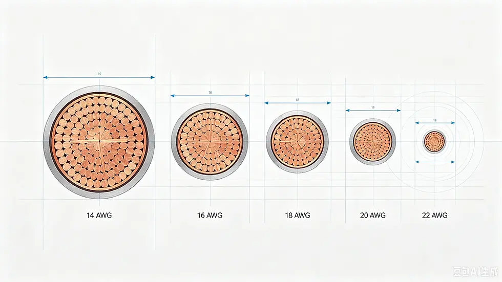
Looking only at conductor dimensions makes the progression easier to understand.
Wire Size | Diameter vs. 14 AWG | Area vs. 14 AWG | General Position |
14 AWG | 100% | 100% | Largest |
16 AWG | ~79% | ~63% | Large |
18 AWG | ~63% | ~40% | Medium |
20 AWG | ~50% | ~25% | Small |
22 AWG | ~40% | ~16% | Smallest |
The reduction in cross-sectional area is especially important. Although the diameter difference between adjacent AWG sizes may not look dramatic, the available conductive area changes substantially.
That is one reason why moving from 14 AWG to 22 AWG is not simply a matter of using a slightly thinner cable. The electrical characteristics of the conductor change significantly as the size decreases.
For practical selection, the basic relationship is therefore:
Smaller AWG number → larger conductor → lower resistance
Larger AWG number → smaller conductor → higher resistance
The next sections will build on this relationship by comparing how those size differences affect current capacity, heat, resistance, and voltage drop in actual applications.
14 AWG vs 16 AWG vs 18 AWG vs 20 AWG vs 22 AWG: Key Differences
The five wire sizes differ in more than physical diameter. As conductor size decreases from 14 AWG to 22 AWG, the available cross-sectional area becomes smaller and electrical resistance increases. These changes affect how much current the conductor can carry, how much voltage is lost along the cable, and how practical the wire is to install.
The table below provides a high-level comparison before looking at each factor in more detail.
Wire Size | Diameter | Area | Relative Resistance | General Electrical Role |
14 AWG | 1.628 mm | 2.08 mm² | Lowest | Higher-current circuits |
16 AWG | 1.291 mm | 1.31 mm² | Low | General power |
18 AWG | 1.024 mm | 0.823 mm² | Moderate | Lighting and small power |
20 AWG | 0.812 mm | 0.519 mm² | Higher | Control and low-current circuits |
22 AWG | 0.644 mm | 0.326 mm² | Highest | Signals and electronics |
These are general relationships rather than standalone installation rules. The actual suitability of a cable also depends on conductor material, insulation, ambient temperature, installation method, cable length, and applicable electrical requirements.
Conductor Size and Electrical Resistance
Conductor size has a direct relationship with resistance. For conductors made from the same material and under comparable conditions, a larger cross-sectional area provides a lower-resistance path for current.
This is why 14 AWG has lower resistance than 16 AWG, while 22 AWG has the highest resistance among the five sizes.
The difference becomes more noticeable as the comparison spans several AWG steps. A short 22 AWG signal connection may perform perfectly well because the current is very low and the distance is limited. The same conductor may become unsuitable for a higher-current power circuit because its higher resistance can produce greater voltage drop and heat.
For copper conductors at approximately 20°C, typical DC resistance values are roughly:
Wire Size | Approx. Resistance per 1000 ft |
14 AWG | 2.53 Ω |
16 AWG | 4.02 Ω |
18 AWG | 6.39 Ω |
20 AWG | 10.15 Ω |
22 AWG | 16.14 Ω |
These values illustrate the trend rather than serving as a universal cable specification. Actual resistance can vary with conductor material, temperature, construction, and manufacturing tolerances.
Current-Carrying Capacity
Current-carrying capacity, or ampacity, is one of the most important practical differences between wire sizes.
In general, a larger conductor can carry more current because it has a larger conductive area and can dissipate heat more effectively. However, AWG size alone does not establish a single universal ampacity.
For example, the allowable current for a conductor can depend on:
conductor material;
insulation temperature rating;
ambient temperature;
number of current-carrying conductors;
installation method;
applicable electrical code.
This is why a statement such as “14 AWG always carries X amps” can be misleading.
Instead, wire size should be evaluated together with the actual installation conditions. A wire that is acceptable in one application may require a different rating or a different size in another.
Voltage Drop and Cable Length

Voltage drop is another major reason to compare wire sizes.
As current travels through a conductor, some voltage is lost because of the conductor's resistance. The longer the cable, the greater the total resistance of the circuit. Higher current also increases voltage drop.
For a simplified DC circuit:
Voltage Drop = Current × Resistance
Because larger conductors have lower resistance, increasing the conductor size can reduce voltage drop.
This becomes especially important when comparing 14 AWG with smaller conductors such as 20 AWG or 22 AWG. A short low-current connection may not need the larger conductor, but the same wire size may produce unacceptable voltage drop over a longer run.
The effect is particularly noticeable in low-voltage systems. Losing 1 V in a 120 V circuit represents a relatively small percentage of the supply voltage, while losing 1 V in a 12 V system represents a much larger percentage.
Flexibility, Weight and Installation Space
Electrical performance is not the only consideration when selecting a wire size.
Larger conductors generally require more material, making the cable heavier and often less flexible. They may also require larger terminals or connectors and more physical space for routing and termination.
Smaller conductors offer the opposite advantages. 20 AWG and 22 AWG can be easier to route through compact equipment, control panels, and electronic assemblies where current requirements are low.
This creates an important tradeoff:
Larger conductor = better electrical performance but potentially more difficult installation.
Smaller conductor = easier handling and lower material use but greater electrical limitations.
The best wire size is therefore not necessarily the largest one available. It is the size that meets the electrical requirements while remaining compatible with the physical installation.
Current Capacity and Electrical Performance
Current capacity should be treated as part of a broader electrical-performance assessment rather than as an isolated number. A wire must be able to carry the required current without exceeding its allowable temperature, but the circuit may also have voltage-drop and connection requirements that influence the final conductor size.
The five AWG sizes in this comparison cover a relatively broad range, from 14 AWG for higher-current applications to 22 AWG for many low-current and signal applications.
Ampacity of 14 AWG Through 22 AWG Wire
There is no single ampacity value that applies to every 14 AWG, 16 AWG, 18 AWG, 20 AWG, or 22 AWG cable.
For example, commonly referenced ampacity tables for copper conductors can provide different allowable currents depending on whether the conductor is evaluated at 60°C, 75°C, or 90°C and under what installation conditions.
For this reason, the following should be treated as general reference ranges rather than universal ratings:
Wire Size | General Current Capability |
14 AWG | Suitable for higher current than the other sizes in this comparison |
16 AWG | Moderate current applications |
18 AWG | Lower-current power and lighting applications |
20 AWG | Low-current applications |
22 AWG | Very low-current, signal, and electronics applications |
For a specific installation, the correct ampacity should come from the applicable standard or manufacturer's cable specification rather than from a generic online chart.
This distinction is particularly important for questions involving 14 AWG at 16 A or 20 A, 18 AWG current capacity, or 20/22 AWG at several amps. The answer cannot be determined responsibly from gauge alone.
Factors That Affect Actual Ampacity
The actual allowable current of a conductor depends on how heat is generated and removed from the cable.
The main factors include conductor material, insulation temperature rating, ambient temperature, installation method, and the number of conductors carrying current together.
For example, two cables with the same 18 AWG copper conductor may have different allowable current ratings if their insulation systems or installation conditions differ.
Temperature is particularly important. As current flows through a conductor, resistive losses generate heat. If that heat cannot dissipate effectively, conductor temperature rises.
Therefore, ampacity should always be evaluated under the conditions in which the cable will actually operate.
The Relationship Between Wire Size, Current and Heat
The relationship between conductor size and heat can be understood through resistance.
The power dissipated as heat in a resistive conductor can be expressed as:
Power Loss = I² × R
where I is current and R is resistance.
This means that increasing current can increase resistive heating rapidly, while a smaller conductor generally has greater resistance.
For example, if the current doubles while resistance remains the same, the theoretical resistive heating increases by a factor of four.
This is why using an undersized conductor for a high-current application can create excessive heating. The issue is not simply that the wire is “thin”; the electrical resistance of the conductor becomes an important part of the thermal behavior of the circuit.
A larger conductor reduces resistance and therefore reduces resistive losses for the same current.
Voltage Drop in Low-Voltage Systems
Voltage drop deserves particular attention in 12 V and 24 V systems.
Consider a simplified example where a circuit loses 1 V because of cable resistance:
In a 120 V system, 1 V represents less than 1% of the nominal voltage.
In a 24 V system, 1 V represents about 4.2%.
In a 12 V system, 1 V represents about 8.3%.
The same physical voltage drop therefore has a much larger effect in a low-voltage circuit.
This is why a conductor that appears adequate based purely on current may still need to be increased in size when the cable run is long or the system voltage is low.
For 12 V and 24 V applications, wire selection should therefore consider both ampacity and allowable voltage drop rather than relying on current capacity alone.
Applications of 14 AWG Through 22 AWG Wire

The best way to understand the differences between 14 AWG, 16 AWG, 18 AWG, 20 AWG, and 22 AWG is to look at how each size is used in real installations. There is no universal “best” AWG size. The appropriate conductor depends on current, voltage, cable length, equipment requirements, and installation conditions.
As a general rule, the larger conductors in this range are better suited to power circuits, while the smaller conductors are more commonly used for lower-current, control, and signal applications.
14 AWG for Higher-Current Power Applications
14 AWG is the largest conductor in this comparison, giving it the lowest resistance and highest general current capability among the five sizes.
It is commonly considered when a circuit requires more current than smaller conductors can reasonably handle or when reducing voltage drop is important.
Typical applications can include certain power circuits, lighting circuits, equipment wiring, and other installations where the required current and applicable electrical requirements make 14 AWG appropriate.
However, choosing 14 AWG does not automatically make a circuit suitable for a particular breaker or load. The conductor must still be evaluated according to its insulation rating, installation conditions, and applicable electrical code.
16 AWG for General Power Applications
16 AWG provides a middle ground between the larger 14 AWG conductor and the smaller 18–22 AWG sizes.
Its larger cross-sectional area than 18 AWG gives it lower resistance, while its smaller physical size can make it easier to handle than 14 AWG.
This makes 16 AWG useful for various general-purpose power, equipment, appliance, and lighting applications where the electrical requirements fall within its permitted range.
For applications where 18 AWG is close to its electrical or voltage-drop limits, moving up to 16 AWG can provide additional margin. The final decision should still be based on the actual load and installation conditions.
18 AWG for Lighting and Small Power Applications
18 AWG sits near the middle of the five sizes and is widely encountered in low- to moderate-current wiring applications.
Its combination of relatively small physical size and reasonable electrical performance makes it useful for lighting, control wiring, small equipment, and other applications where the current requirement is limited.
Compared with 22 AWG, 18 AWG has substantially more conductor area and lower resistance. This makes it more appropriate when the circuit carries meaningful power rather than primarily transmitting a low-current signal.
At the same time, 18 AWG should not automatically be treated as a replacement for a larger conductor. Current, distance, insulation, and installation conditions still determine whether the size is appropriate.
20 AWG for Control and Low-Current Applications
20 AWG is smaller than 18 AWG and has correspondingly higher resistance. It is therefore generally better suited to lower-current applications where the electrical load and cable length are limited.
Typical applications may include control circuits, electronic equipment, instrumentation, and other low-current wiring.
The relatively small conductor can also be useful where installation space is limited. However, the smaller conductor area means voltage drop can become significant sooner, particularly in low-voltage systems or longer cable runs.
22 AWG for Signals, Sensors and Electronics
22 AWG is the smallest conductor in this comparison. Its small diameter makes it particularly useful where low current, compact dimensions, and flexibility are more important than high power capacity.
Common applications include signal wiring, sensors, communication-related circuits, electronics, control systems, and other low-current applications.
Whether 22 AWG is suitable for a power circuit depends on the actual current, cable length, conductor construction, insulation, and allowable voltage drop. It should not be selected simply because the equipment operates at a low voltage.
For example, a 12 V circuit can still require substantial current if the connected load consumes significant power. In such cases, the small conductor may produce excessive voltage drop or heating.
Selecting the Right Wire Size

Choosing between these five wire sizes should be treated as a design decision rather than a simple comparison of physical dimensions. The correct conductor needs to satisfy the electrical requirements while also working with the physical installation.
A useful approach is to consider the load first, then evaluate cable length, voltage drop, installation conditions, and compatibility with the equipment.
Matching Wire Size to Current Requirements
The first consideration is the amount of current the circuit is expected to carry.
As a general principle, a larger conductor provides greater current-carrying capability than a smaller conductor under comparable conditions. However, the actual allowable current must come from the applicable ampacity requirements for the specific cable and installation.
For example, the fact that 14 AWG is larger than 18 AWG does not mean that every 14 AWG cable can automatically be used on any high-current circuit.
Likewise, the fact that 22 AWG is commonly used for signals does not mean that it can never carry power. The actual current and installation conditions still determine suitability.
The correct process is therefore:
Determine load current → check applicable ampacity → evaluate voltage drop → confirm installation requirements.
Accounting for Cable Length and Voltage Drop
Cable length becomes increasingly important as the distance between the power source and load increases.
A longer conductor has greater total resistance. If the current remains the same, the voltage drop therefore increases with cable length.
This can make a larger conductor necessary even when the current itself is within the basic ampacity of a smaller wire.
For example, a short 18 AWG connection may perform well at a particular load, while a much longer run carrying the same current may benefit from 16 AWG or 14 AWG to reduce voltage drop.
The same principle applies when comparing 20 AWG and 22 AWG. A small difference that is insignificant in a short electronic connection can become important when the cable is substantially longer.
Selecting Wire for 12V and 24V Systems
Low-voltage systems require particular attention because voltage drop represents a larger percentage of the available supply voltage.
At 12 V, even a relatively small voltage loss can represent a significant percentage of the system voltage. At 24 V, the same voltage loss has a smaller proportional effect, but it can still matter for sensitive equipment or long cable runs.
For this reason, 12 V and 24 V applications should not be sized using current alone.
A practical selection process should consider:
Consideration | Why It Matters |
Load current | Determines the required current-carrying capability |
Cable length | Longer runs increase resistance |
System voltage | Determines how significant a given voltage drop is |
Allowable voltage drop | Establishes how much loss the system can tolerate |
Installation method | Can affect allowable ampacity |
Conductor material | Affects resistance and electrical performance |
This is particularly important for applications such as LED lighting, battery-powered equipment, automotive-style circuits, and other low-voltage systems.
Balancing Electrical Performance and Installation Requirements
The largest conductor is not automatically the best conductor for every application.
Moving from 22 AWG to 14 AWG can significantly reduce resistance, but it also increases conductor size, material usage, weight, and often cost. A larger wire may also be harder to route through compact equipment or terminate in connectors designed for smaller conductors.
On the other hand, selecting a smaller conductor purely to reduce cost can create excessive voltage drop, heating, or installation problems if the circuit requirements exceed its capabilities.
The goal is to find the smallest conductor that safely and reliably satisfies the electrical and installation requirements.
In practice, that means considering four factors together:
Current + distance + voltage drop + installation conditions
rather than choosing a wire based on AWG number alone.
Wire Gauge Substitution and Compatibility
Sometimes an installation calls for one wire size, but a different AWG size is available. This raises an important distinction: a larger conductor may offer better electrical performance, but that does not automatically make it a suitable replacement in every installation.
When changing from one wire gauge to another, both electrical and mechanical compatibility should be checked. The conductor must be appropriate for the circuit, while the finished cable must also work with the terminals, connectors, equipment, and installation method.
Using a Larger Conductor in Place of a Smaller One
In general, moving to a larger conductor can reduce resistance and improve voltage-drop performance when the other cable characteristics remain appropriate.
For example, replacing an 18 AWG conductor with 16 AWG or 14 AWG may provide more conductive area and lower resistance. However, the fact that the replacement wire is electrically larger does not mean the substitution is automatically acceptable.
The complete circuit still needs to be evaluated.
A larger conductor may be reasonable when:
the terminal can accept the larger conductor;
the insulation and cable construction meet the application requirements;
the larger wire can be routed properly;
the equipment manufacturer permits the conductor size;
the applicable electrical requirements are satisfied.
This is why “larger is electrically better” and “larger is always interchangeable” are not the same statement.
Electrical and Mechanical Considerations When Changing Wire Size
Wire substitution involves more than conductor resistance and ampacity.
A change from 18 AWG to 16 AWG, for example, changes the conductor diameter and may also change the overall cable diameter. That can affect how the wire fits into terminals, connectors, cable glands, conduit, or other installation components.
The insulation type also matters. Two conductors with the same AWG size may have very different outside diameters depending on insulation thickness and cable construction.
For this reason, a substitution should be checked from both sides:
Electrical Consideration | Mechanical Consideration |
Current capacity | Terminal size |
Resistance | Connector compatibility |
Voltage drop | Cable routing space |
Conductor material | Bend radius |
Insulation temperature rating | Strain relief |
Installation conditions | Overall cable diameter |
This is particularly important in compact equipment where the connector is designed around a specific conductor range.
Terminal, Connector and Installation Compatibility
A conductor can be electrically suitable but mechanically incompatible.
For example, a terminal designed for 18–22 AWG conductors may not properly accommodate a much larger 14 AWG conductor. Forcing a larger conductor into an unsuitable terminal can create poor contact, unreliable connections, or damage to the termination.
The same principle applies in the opposite direction. A connector designed for larger conductors may not properly secure a much smaller wire.
Before substituting a wire size, check the specified conductor range of:
terminals;
connectors;
circuit breakers;
terminal blocks;
crimp contacts;
cable glands;
strain-relief components.
The finished cable also needs to fit the available installation space and maintain the required mechanical protection.
Wire Gauge and Circuit Protection
Wire sizing and circuit protection are closely related because the protective device must protect the conductor as well as the connected load.
A breaker or fuse is not simply selected based on the maximum current the equipment might consume. The conductor's allowable ampacity and the requirements of the applicable electrical code also have to be considered.
This becomes especially important when comparing smaller conductors such as 14 AWG with circuits protected by higher-rated breakers.
Matching Conductor Ampacity With Breaker Rating
A circuit protective device is intended to limit current to a level that protects the circuit conductors and connected equipment under the applicable requirements.
Therefore, increasing the breaker rating does not automatically make a smaller wire acceptable.
For example, changing a circuit from a lower-rated breaker to a 20 A breaker should not be treated as a simple equipment upgrade if the existing conductor is not permitted for that circuit configuration.
The correct relationship is:
Load requirements → conductor sizing → circuit protection → applicable code
rather than:
Breaker rating → choose any wire that fits
This distinction is important when evaluating questions about 14 AWG, 16 AWG, and higher-current residential circuits.
Residential Circuit Requirements
Residential wiring requires particular attention because conductor size and circuit protection are governed by electrical codes and installation rules.
For example, questions about whether 14 AWG can be used on a 20 A residential circuit cannot be answered from the AWG number alone. The applicable code, circuit configuration, conductor characteristics, installation conditions, and permitted uses all have to be considered.
In the United States, the National Electrical Code (NEC) provides the framework used for many residential electrical installations, but local jurisdictions can adopt and amend code requirements.
Therefore, a general AWG comparison should not be treated as a substitute for the requirements governing a specific residential project.
GFCI Applications and Conductor Sizing
GFCI protection adds another layer to circuit design, but a GFCI device does not change the basic requirements for conductor sizing.
A GFCI is designed to detect certain ground-fault conditions and disconnect the circuit. It does not make an undersized conductor suitable for a higher-current circuit.
When selecting a GFCI-protected circuit, the conductor size, circuit rating, device rating, load, and applicable installation requirements should all be considered together.
This is why questions such as whether a particular GFCI can be installed with 14 AWG should be evaluated as a complete circuit-design question, rather than based on the GFCI device alone.
Why Local Electrical Codes Still Apply
AWG charts are useful for understanding conductor size, resistance, and general electrical behavior, but they do not replace electrical codes.
The requirements for a particular installation can vary according to:
country or region;
electrical code edition;
residential or commercial application;
conductor insulation;
installation method;
ambient conditions;
number of current-carrying conductors;
circuit type.
For U.S. residential projects, the applicable NEC requirements and local amendments should be checked before selecting a conductor or modifying a circuit.
For commercial, industrial, automotive, solar, or other specialized applications, the relevant standards and project specifications may be different.
The practical rule is simple: use AWG information to understand the wire, but use the applicable electrical standard to determine whether that wire is permitted for the actual installation.
Problems Caused by Incorrect Wire Sizing
Selecting the wrong wire size can affect both safety and system performance. The problem is not limited to using a conductor that is too small. An unnecessarily large conductor can also create mechanical, installation, and cost issues.
The right approach is to select a conductor that provides sufficient electrical capacity and acceptable voltage-drop performance while remaining compatible with the installation.
Risks of Undersized Conductors
An undersized conductor has less conductive area than the application requires. When current flows through the conductor, its resistance produces heat, and that heat increases as current increases.
If the conductor is not adequately sized for the application, several problems can occur:
excessive conductor heating;
increased voltage drop;
reduced equipment performance;
energy losses;
deterioration of insulation over time;
potential damage under abnormal or sustained overload conditions.
Voltage drop can also become a significant problem before the conductor reaches an obvious thermal limit. This is particularly relevant in 12 V and 24 V systems, where even a relatively small voltage loss represents a larger percentage of the available supply voltage.
For example, using 22 AWG simply because the cable is physically convenient may not be appropriate for a power circuit that requires substantially more current. The conductor's small cross-sectional area and higher resistance may result in unacceptable electrical performance.
Limitations of Oversized Conductors
Using a conductor larger than necessary is generally less problematic from a resistance perspective, but it does not mean oversized wire is always the best choice.
A larger conductor can introduce practical disadvantages:
higher material cost;
increased cable weight;
reduced flexibility;
larger bend radius;
difficulty fitting terminals or connectors;
increased installation space requirements.
An oversized conductor can also create a termination problem if the equipment is designed for a particular conductor range.
For example, replacing an 18 AWG wire with 14 AWG may reduce resistance, but if the terminal or connector cannot properly accommodate 14 AWG, the larger conductor may actually make the installation less reliable.
The goal is therefore not to select the largest possible wire, but to select a wire that provides the required electrical performance while remaining mechanically and economically practical.
Balancing Safety, Performance and Cost
Good wire selection is ultimately a balance between several competing requirements.
Factor | Smaller Wire | Larger Wire |
Conductor resistance | Higher | Lower |
Voltage-drop performance | Generally worse | Generally better |
Current capability | Lower | Higher |
Flexibility | Generally better | Generally lower |
Weight | Lower | Higher |
Material cost | Lower | Higher |
Installation space | Less | More |
This is why neither “always use the smallest wire” nor “always use the largest wire” is a sound design strategy.
A suitable wire should meet the required ampacity, maintain acceptable voltage drop, satisfy the applicable electrical requirements, and work with the physical installation.
For many applications, the most efficient selection is the smallest conductor that safely meets all of the actual requirements.
Common Wire Gauge Selection Mistakes
Wire gauge comparisons often become confusing because people focus on one specification and overlook the other factors that determine whether a cable is appropriate.
The most common mistakes involve treating AWG, ampacity, and voltage drop as interchangeable concepts when they are actually related but different.
Choosing Wire Based Only on Ampacity
A wire may have sufficient ampacity for a particular current and still produce too much voltage drop over a long distance.
This is especially important for low-voltage systems.
For example, a conductor might be thermally capable of carrying a given current, but if the cable run is long, its resistance can cause a significant reduction in the voltage delivered to the load.
Wire selection should therefore consider both:
Current capacity + voltage-drop requirements
rather than ampacity alone.
Ignoring Voltage Drop
Voltage drop becomes increasingly important as cable length increases.
The resistance of the complete circuit depends on the length of the conductor path. In many DC applications, the calculation needs to account for both the outgoing and return conductors.
This is why the same 18 AWG wire may be perfectly reasonable for a short connection but less suitable for a long run carrying the same current.
The issue is not that the wire itself has changed. The electrical conditions of the installation have changed.
Assuming a Larger Conductor Is Always Better
A larger conductor generally provides lower resistance and greater current capability, but that does not make it automatically appropriate.
Oversizing can create problems with:
terminals;
connectors;
cable routing;
bend radius;
equipment compatibility;
installation cost.
The correct question is not:
“What is the biggest wire I can use?”
It is:
“What conductor size provides the required electrical performance and fits the actual installation?”
Selecting Wire Based Only on Cost
Choosing a smaller wire simply because it costs less can create larger costs later if the conductor produces excessive voltage drop, requires replacement, or causes equipment to operate inefficiently.
At the same time, unnecessarily using a much larger conductor increases material and installation costs without necessarily providing a meaningful benefit.
A better approach is to evaluate the complete application first and then select the most appropriate size.
For a comparison covering 14 AWG through 22 AWG, this means considering the conductor size in relation to current, cable length, voltage, application, installation method, and circuit protection rather than selecting a gauge from price alone.
Frequently Asked Questions
The questions below address the most common practical issues that come up when comparing 14 AWG, 16 AWG, 18 AWG, 20 AWG, and 22 AWG wire. The answers should be treated as general guidance; the actual suitability of a wire depends on conductor material, insulation, installation conditions, circuit requirements, and applicable electrical codes.
Q1: Is 18 AWG thicker than 22 AWG?
Yes. 18 AWG is thicker than 22 AWG. Standard AWG dimensions put the conductor diameter at approximately 1.024 mm for 18 AWG and 0.644 mm for 22 AWG. Because a smaller AWG number represents a larger conductor, 18 AWG also has a greater cross-sectional area and lower resistance than 22 AWG.
Q2: Can 22 AWG handle 3 amps?
22 AWG should not be assumed to safely handle 3 amps in every application. Its allowable current depends on the conductor material, insulation, ambient temperature, installation conditions, and applicable standards. Because 22 AWG has a relatively small conductor area, voltage drop and heating can become important at several amps, particularly over longer runs.
Q3: Can 20 AWG handle 3 amps?
20 AWG may be suitable for certain 3 A applications depending on the cable construction, length, installation conditions, and allowable voltage drop. Ampacity should be checked against the specific cable specification or applicable standard rather than using AWG size alone. For a long 12 V or 24 V run, voltage drop may require a larger conductor even when the current itself appears acceptable.
Q4: Can 14 AWG handle 16 amps?
14 AWG can be suitable for some applications carrying 16 A, but the answer depends on the specific conductor and installation conditions. The applicable ampacity requirements, insulation temperature rating, number of current-carrying conductors, ambient temperature, and circuit type should all be considered before selecting the wire.
For residential circuits, the applicable electrical code must also be checked rather than relying on a generic ampacity number.
Q5: Can 14 AWG handle 30 amps?
14 AWG should not automatically be treated as a 30 A conductor. Whether a particular 14 AWG conductor is permitted to carry 30 A depends on the applicable code, conductor characteristics, and installation conditions. In many common residential applications, 14 AWG is not used as a general-purpose 30 A circuit conductor.
A higher-rated breaker should never be used simply because the wire physically fits the terminal. Circuit protection must be coordinated with the permitted conductor ampacity and the applicable electrical requirements.
Q6: How many amps can 18 AWG wire carry?
There is no single universal ampacity for 18 AWG wire. The allowable current depends on conductor material, insulation temperature rating, installation method, ambient conditions, and the applicable standard.
For low-current electronics, control wiring, and short connections, 18 AWG can be practical. For higher-current or longer-distance applications, both ampacity and voltage drop should be evaluated before selecting the conductor.
Q7: Can 14 AWG replace 18 AWG wire?
A 14 AWG conductor is physically larger than 18 AWG and generally has lower resistance, so it can provide better electrical performance when the larger conductor is otherwise compatible with the application.
However, replacing 18 AWG with 14 AWG is not automatically acceptable. The larger conductor must fit the terminal or connector, meet the cable and insulation requirements, and be suitable for the equipment and installation method.
Q8: Can 16 AWG replace 18 AWG wire?
16 AWG is larger than 18 AWG, so it generally provides lower resistance and greater conductive area. It can sometimes be used in place of 18 AWG when the installation allows the larger conductor.
The main issue is compatibility. Terminals, connectors, crimp contacts, and equipment may specify a particular conductor-size range. The replacement wire must also meet the required insulation and environmental specifications.
Q9: When is 22 AWG wire typically used?
22 AWG is commonly used where the current requirement is relatively low and compact wiring is beneficial. Typical applications include signals, sensors, control circuits, electronics, instrumentation, and communication-related wiring.
It can also be used for certain low-power applications, but the actual current, cable length, voltage drop, and cable construction should be evaluated before using it for power transmission.
Q10: How should I choose between 14 AWG and 22 AWG?
Start with the load current and cable length, then check ampacity and voltage drop under the actual installation conditions.
14 AWG is much larger and has substantially lower resistance than 22 AWG, making it more suitable for higher-current or longer power runs. 22 AWG is much smaller and is often more appropriate for low-current signals, sensors, control wiring, and compact electronic applications.
The correct choice is therefore not simply the largest or smallest wire. It is the conductor that provides sufficient electrical performance while remaining compatible with the installation.
Conclusion
The difference between 14 AWG, 16 AWG, 18 AWG, 20 AWG, and 22 AWG comes down to conductor size and the electrical and mechanical characteristics that follow from it.
14 AWG is the largest conductor in this group, while 22 AWG is the smallest. As the AWG number increases, conductor area decreases and resistance generally increases. That affects current capacity, voltage drop, heat generation, and the types of applications for which each size is practical.
For a simple comparison:
14 AWG: larger conductor for higher-current applications
16 AWG: general-purpose power applications
18 AWG: lighting, control, and small-power applications
20 AWG: low-current control and electronics
22 AWG: signals, sensors, and other low-current applications
However, AWG should never be the only factor in wire selection. Current, cable length, voltage drop, insulation, installation conditions, circuit protection, connectors, and applicable electrical codes all need to be considered.
The most reliable approach is to determine the actual electrical requirements first and then select the appropriate conductor size rather than choosing a wire based on gauge alone.


Comments